I don't have time to get to my printer for the next week or so, but as soon as I can get back I'm definitely trying the diluted PVA on top of glass to get the PLA to stick.
I was having lunch with a friend Friday, whining about my problems getting the blue PLA to adhere, and he said (paraphrasing here), "Isn't there some kind of glue or coating you can put down on the surface to get it to stick?" Doh!! Suddenly all the posts I had read through that talk about using a PVA and water mixture seemed much more important, and I couldn't wait to get back to the forums and blogs and find out how to make my own dilutions and get back to printing.
I think I had dismissed those methods before because my experience with the gold PLA on glass over a HBP had been so positive. The thought of having to do some secondary operation and paint on a coating of some type seemed like an unnecessary extra amount of work, so I had put those methods out of my mind while I tried to find the right combination of extruder and HBP temperatures to get the blue PLA to adhere. After a few weeks of frustration, though, the idea of painting on a film of diluted PLA seems like a very small price to pay to get the new spool of PLA to stick without problems.
I picked up some PVA glue (Elmer's) at Wal-Mart a couple of days ago. I went with the classic tube of white glue with the orange top (http://www.elmers.com/product/detail/E1322?filterPath=school). They also were selling a spray-on product that seemed interesting (http://www.elmers.com/product/detail/E422?filterPath=craft). I'm curious if anyone has tried this, since spraying on a coating of glue could be a very quick and easy way to prep the glass surface.
I've decided to first try a dilution of 1:8 PVA:water on a cooled glass surface. I've seen posts about mixtures stronger than that resulting in the parts not coming off of the glass (without taking some of the glass with them, at least): http://forums.reprap.org/read.php?262,141761,141761 I've also seen posts suggesting that using this ratio on a heated glass plate works well: http://richrap.blogspot.com.au/2012/06/more-scrap-art-gearboxes-and-panelmax.html
I'm a little worried that the piece of glass I have is not very tough. I got it out of a flatbed scanner that I was throwing away. I will try the cooled glass coated in PVA mixture, and if that doesn't work I will first try to thicken the mixture. If that still doesn't work I will use the coating over a heated build surface. Either way, I have a plan with potential for success, and that's really all I need to stay excited about the next steps :)
D
Sunday, September 30, 2012
Friday, September 28, 2012
Tangled Up In Blue PLA
After several hours of frustration trying to get the blue PLA I ordered from Amazon to stick to the heated build plate, I finally have started to figure this stuff out.
To those of you who have been 3D printing for a while, my solution may seem obvious, but I want to briefly explain how I came to the correct settings. Hopefully, by doing this I will both 1) save other people new to 3D printing and RepRap's wasted time and trouble, and 2) remind myself to look out for similar behavior in the future and avoid getting stuck on the same issue.
I had run out of gold PLA, which was the first spool of material that I had ordered and run through my MendelMax 1.5 printer. Here is a link to the gold PLA I ordered: Gold PLA 3mm from Amazon.com
I was very satisfied with this material's performance (I didn't know any better anyway, it was my first spool of material), and free 2-day shipping with Amazon Prime is just too tempting. So for my next spool of material I also ordered from Amazon.com, except I got blue material, and it was from a different supplier: Blue PLA 3mm from Amazon.com
Here is a picture of the material over my machine:

I knew I would probably need to adjust the extrusion temperature when I switched materials, so when I started to print with the blue PLA I used a method described on the calibration page of the RepRap.org site. The basic idea is to set the extruder temperature lower and lower and keep trying to extrude material. When you reach a temperature low enough that the extruder cannot push material through the nozzle, increase the temperature by 5 degrees and that's the temperature to use for printing.
This method did now work for me.
I had been printing the gold PLA at around 161 C. I think I did arrive at that temperature using the method described above, and I had good results with this material (barring some times when I had other settings messed up) for several weeks. When I tried the same method with the new spool of blue PLA, I came out with a temperature almost 10 degrees lower. As mentioned in previous posts, though, at this temperature the material was not sticking to the build plate.
I tried increasing the temperature of the extruder and build plate, sometimes together, sometimes separately, and I tried a range of temperatures for each from as low to as high as I thought might be reasonable. I think I tried a build plate temperature from 50 C up to 80 C, and a material temp as low as 150 C and as high as 175 C. I also kept cleaning the glass over and over, wondering if that had something to do with the failures.
At one point I thought I had it, and a print got through the first layer of a large plate of parts for the lathe I'm printing, but when I came back down after the print had gone through maybe 10% of the second layer, I found that some of the pieces had lifted off and stuck to the hot end, and this is what I pulled out of the machine:

That was about a week ago, after over a full week of trying with no success. Finally, this past Tuesday on a whim I decided to jack the temperatures way up, to 181 C on the extruder and 73 C on the HBP. I was shocked to see how well it worked--I felt like I had come back off the DL just in time for the playoffs.
The 181 C came from posts I had read online about printing PLA around these temperatures. It seemed like I was printing the gold PLA at a relatively low temperature compared to other people, so I really thought my machine just wasn't reading the temperature correctly. I guessed the 161 C I had been using for gold was probably more like 175 C in reality, so going much higher than that would be a bad idea. Also, I had used the method described above to find the optimum temperature, and that lead me to believe that the blue PLA should be printed at a temperature something like 30 degrees cooler than the 181 C that eventually worked.
The 73 C temperature on the HBP wasn't such a stretch, since I had noticed that up until this temperature range it did seem to help with the issues I had been having. It just couldn't solve them completely without me also adjusting the extruder temperature.
Right now I'm printing Plate 2 from the Lathe prints, and itseems to be doing great is mostly doing great but there was some trouble in a few areas on the first layer--I will see if it can recover.

Seeing it run at 181 C, it's hard to imagine why I did not know to go to this high of a temperature before. I was going on what I thought was a proven way of calculating optimal extrusion temperature, and it ended up causing me to not try high enough temperatures.
I also have been cleaning the glass with 91% Isopropyl Alcohol (rubbing alcohol). This seems to be working well, although I have no real way to separate its effect from the other variables that I have been working with.
So, in summary, if you are having trouble with adhesion of the first layer, you should try higher temperature to see if that allows the material to bond more strongly with the surface of the glass you're printing on. In the end, there are lots of variables that come into play, but at least you will give yourself a chance to reach a temp that works, even if it seems far outside of the range suggested by using the min possible extrusion temperature + 5 degrees.
D
PS - Sorry for the title, just couldn't help myself . . .
To those of you who have been 3D printing for a while, my solution may seem obvious, but I want to briefly explain how I came to the correct settings. Hopefully, by doing this I will both 1) save other people new to 3D printing and RepRap's wasted time and trouble, and 2) remind myself to look out for similar behavior in the future and avoid getting stuck on the same issue.
I had run out of gold PLA, which was the first spool of material that I had ordered and run through my MendelMax 1.5 printer. Here is a link to the gold PLA I ordered: Gold PLA 3mm from Amazon.com
I was very satisfied with this material's performance (I didn't know any better anyway, it was my first spool of material), and free 2-day shipping with Amazon Prime is just too tempting. So for my next spool of material I also ordered from Amazon.com, except I got blue material, and it was from a different supplier: Blue PLA 3mm from Amazon.com
Here is a picture of the material over my machine:

Spool of Blue PLA Over My Machine
I knew I would probably need to adjust the extrusion temperature when I switched materials, so when I started to print with the blue PLA I used a method described on the calibration page of the RepRap.org site. The basic idea is to set the extruder temperature lower and lower and keep trying to extrude material. When you reach a temperature low enough that the extruder cannot push material through the nozzle, increase the temperature by 5 degrees and that's the temperature to use for printing.
This method did now work for me.
I had been printing the gold PLA at around 161 C. I think I did arrive at that temperature using the method described above, and I had good results with this material (barring some times when I had other settings messed up) for several weeks. When I tried the same method with the new spool of blue PLA, I came out with a temperature almost 10 degrees lower. As mentioned in previous posts, though, at this temperature the material was not sticking to the build plate.
I tried increasing the temperature of the extruder and build plate, sometimes together, sometimes separately, and I tried a range of temperatures for each from as low to as high as I thought might be reasonable. I think I tried a build plate temperature from 50 C up to 80 C, and a material temp as low as 150 C and as high as 175 C. I also kept cleaning the glass over and over, wondering if that had something to do with the failures.
At one point I thought I had it, and a print got through the first layer of a large plate of parts for the lathe I'm printing, but when I came back down after the print had gone through maybe 10% of the second layer, I found that some of the pieces had lifted off and stuck to the hot end, and this is what I pulled out of the machine:

Melted Glob From Parts Not Adhering to Build Plate
That was about a week ago, after over a full week of trying with no success. Finally, this past Tuesday on a whim I decided to jack the temperatures way up, to 181 C on the extruder and 73 C on the HBP. I was shocked to see how well it worked--I felt like I had come back off the DL just in time for the playoffs.
The 181 C came from posts I had read online about printing PLA around these temperatures. It seemed like I was printing the gold PLA at a relatively low temperature compared to other people, so I really thought my machine just wasn't reading the temperature correctly. I guessed the 161 C I had been using for gold was probably more like 175 C in reality, so going much higher than that would be a bad idea. Also, I had used the method described above to find the optimum temperature, and that lead me to believe that the blue PLA should be printed at a temperature something like 30 degrees cooler than the 181 C that eventually worked.
The 73 C temperature on the HBP wasn't such a stretch, since I had noticed that up until this temperature range it did seem to help with the issues I had been having. It just couldn't solve them completely without me also adjusting the extruder temperature.
Right now I'm printing Plate 2 from the Lathe prints, and it

Printing Lathe Parts with Blue PLA
Seeing it run at 181 C, it's hard to imagine why I did not know to go to this high of a temperature before. I was going on what I thought was a proven way of calculating optimal extrusion temperature, and it ended up causing me to not try high enough temperatures.
I also have been cleaning the glass with 91% Isopropyl Alcohol (rubbing alcohol). This seems to be working well, although I have no real way to separate its effect from the other variables that I have been working with.
So, in summary, if you are having trouble with adhesion of the first layer, you should try higher temperature to see if that allows the material to bond more strongly with the surface of the glass you're printing on. In the end, there are lots of variables that come into play, but at least you will give yourself a chance to reach a temp that works, even if it seems far outside of the range suggested by using the min possible extrusion temperature + 5 degrees.
D
PS - Sorry for the title, just couldn't help myself . . .
Monday, September 24, 2012
The Blog Is Not Dead . . .
Since the last post about a week ago, I've spent almost all of my time outside of work and family responsibilities working on two new design ideas. 3D printing has taken a temporary back seat, but I did try to get back into the lathe printing this afternoon.
One other thing that has kept me from printing as much this week is the continued difficulty I'm having getting the blue PLA to adhere to the heated build plate. I've tried varying the first layer height (adjusting the end stop), adjusting the extrusion and HBP temperatures, and this afternoon I decided to print the first layer extremely slow--I think the setting was a speed factor for the first layer of 0.05. That's crawling.
This very slow speed seemed to be doing the trick, but when I came back down to check on the print a few of the parts had lifted and the extruder had a huge glob of blue PLA on it . . . so I'm still in the dark here. When I get some time I will hit the forums and take a closer look at the issue, but for now I need to tackle these two new projects I have going and move them along.
What's great about it all is that the 3D printer will soon become key to the further development of the two projects, so it all comes together in the end. I'm very frustrated with the blue PLA troubles, but I'm very excited to know that I can build prototypes and try out my ideas as soon as I finish the initial designs. Awesome :)
D
Sunday, September 16, 2012
Printing A Lathe - Only 4 Plates To Go
After completing the first plate Friday night, I estimated by looking at the spool of PLA over the printer that I only had enough material left to complete plate 5, the smallest (in terms of material requirements) of the four remaining plates of parts.


Plate 5 From The Lathe Print
Unfortunately, the part in the lower left corner with 6 spokes and knobs on the ends did not slice correctly. I didn't have enough time yesterday morning to figure out why, but when I was able to start working again yesterday afternoon I installed NetFabb Studio http://www.netfabb.com/ and loaded the .stl file that SketchUp exported to identify the problem.
NetFabb looks like a very powerful piece of software, with capabilities for 3D part design, tool path creation, even 3D printer machine operation. At this time, I'm only using it to analyze .stl files for errors or holes.
NetFabb clearly identified the issues with the .stl file by highlighting them in burgundy. The screenshot below is of the part after I had made some changes to try and simplify it.

NetFabb Screenshot With Error Faces Highlighted
After more redesign is SketchUp, export, check in NetFabb, redesign in SketchUp, export, repeat, repeat, I finally got to a part that had no holes and would slice properly so that I could run the print. I learned a lot about design elements and SketchUp behaviors to avoid so that the .stl comes out solid and will slice properly, but it did take up a large chunk of my available 3D printing time yesterday.
Last night I finally was able to restart printing plate 5. I went upstairs while the bottom layer printed (since this can take 30 - 45 minutes with my settings and the size of these prints) and then came back down to turn on the fans around the machine for the remainder of the print. I reached over to turn on a small portable fan I have sitting near the printer on my work bench, and the instant that I flipped the switch, the printer froze!
The hot end was still heating (the LED connected to the hot end output was flashing on and off), and the bed was turning on and off, but none of the motors were moving at all. I tried to pause and resume the print in Pronterface, and after clicking on a few more movement commands with no response from the printer the software hung up. I was out of time anyway, so I killed the software and the power to the printer and went back upstairs to sleep.
This morning I was very, very happy to see that I was able to connect to the printer again, so I new the board wasn't totally fried. When I tried moving the motors, though, there was no response, and the software seemed to hang again. I was able to turn the hot end and HBP on and off, so I decided that there was something wrong in the code dealing with motor movement, and Pronterface was looking for a response from the board and not getting it and thus becoming unresponsive itself. I fired up the Arduino software, re-flashed Marlin onto the board, restarted Pronterface and bingo--all is again right with the world.
So now I'm printing plate 5 again, and have made it past the first layer and turning the fan on. I was very scared when I flipped the switch, I have to admit. I have no idea why turning on the fan messed with the board--it could have been a dirty spike in the power line, some strange EMI issue, or I could have bumped against the Arduino or RAMPS boards or cables and shorted something out.
I know enough about controls and electronics to go ahead and file this problem into the "avoid" rather than "solve" category. I hope to get a fan duct printed and installed at some point, and can then start using a much more focused, less powerful cooling fan that is turned on automatically by the software after the first layer. That would mean a much more predictable and less severe change in power requirements, and I hopefully will not see this type of failure again.
D
Saturday, September 15, 2012
Printing A Lathe - Only 5 Plates To Go
I was able to get back to the MendelMax here in the basement late last night. After completing the parts for the 3-Jaw chuck (see previous post), it was time to move on to the rest of the lathe parts. I had already printed an upright before, but the quality was poor due to the trace width issues I was having at the time.
I started by loading the entire lathe assembly file (from here: http://www.thingiverse.com/thing:12472) in SketchUp and identified the pieces I had already printed. I am not using the 4-Jaw chuck shown in the assembly file below, but I went ahead and deleted those anyway since my 3-Jaw chuck was complete.

Then I drew a rectangle representing the maximum build area of my machine, and offset it in by 5mm for the offset of the skirt that Slic3r prints around the part.

I like leaving the gray face to give me something to position the components on when I'm building up the plate. It's easy to delete at the end.
Once this area is defined, it's just a matter of arranging the components just as you would like them to print out. One thing to note is that you want to change the individual parts to components (triple-click on a part to highlight all its edges and faces, right click --> Make Component). This makes it very easy to move them around, and if you happen to position to components so that they interfere with each other, SketchUp does not try to combine the intersecting geometry.
Once I fill up the build area, I save the file as something like [descriptive file name]_Plate1.skp. I then save it as the next plate [descriptive file name]_Plate2.skp, and go back and delete all of the parts that do not get printed in the first plate file. What I'm left with is something like this--which is the first plate of 5 that I need to print to complete the lathe.

Then in the next plate file I start by deleting all of the parts that were printed in the first, move a new batch of components onto the build area, save it as the next plate, go back and delete the unneeded parts, and then repeat. The five plates I ended up with for the lathe print are shown below.


One thing that I think is so cool every time I do this is that I can fill up the build area with extra copies of parts that I think might not print well or that might wear out or break over time and need to be replaced. Since each plate takes around 7 or 8 hours to print, adding another gear or three and 1/2 an hour to the print time is hardly noticeable. It's like getting spare parts for free . . .
I started the first plate last night around 1am, so it was still going when I got down here this morning. Here is what the print looks like so far:

The print in the lower right corner of the image above with a cylinder and two rectangular pieces with two holes in each has one small issue. The corners of the rectangular section closest to the front edge of the HBP have lifted off of the glass surface.

None of the other parts have lifted, and I think I know why it happened to this particular part--this is directly in front of a fan that I have blowing on the build area. I positioned the fan here because I knew there were two taller parts at this location (see the image of Plate 1 above), and I wanted to make sure each layer was cooling sufficiently when the total print area on each layer started to get small. If the lift and warp on this particular part turns out to be a problem, I can always make another . . .
Hope to start the second plate printing just as soon as this first one finishes, so that I can get another two plates printed in the next 24 hours. IF everything goes well, I can complete the print of the lathe parts before I leave for work on Monday.
One thing that has to happen before that is a switch to a new color of PLA. I'm almost through my first 1 kg spool of 3 mm filament . . . feels like some kind of a milestone. I decided on blue for my next color. Hopefully I can dial in the correct printing temperature for the new color quickly (from what I read the optimal extrusion temperature varies even from color to color) and keep right on printing . . .
D
Thursday, September 13, 2012
Printing A Lathe - 3-Jaw Chuck
The print of the 3-Jaw Chuck that I started last night around midnight completed this morning after I had to leave for work. Everything looks like it came out great. This print was a plate full of chuck pieces, as shown here:

Here are a couple of shots of the parts actually printing:


When I got home tonight I turned everything off and had to leave the printed pieces on the printer and come upstairs, but it looked like there were no major issues. During the print I had a lot of air blowing across the print to keep the parts from warping, especially where they were positioned close to each other. I did notice some strings on the parts. I think this can be caused by too much cooling/too low material temp.
Also, below is a shot of the first layer of one of my prints.

I've been setting the Z-axis end stop low enough to cause the first layer to be squished against the glass. This leads to a slight lip on the bottom surface of the print, but to me that is well worth it to make sure that the parts don't come off of the HBP before the print is complete.
.JPG)
The last thing to share tonight is two videos of this large plate of items being printed. Please see below and on YouTube.
This second video is very similar to the first, but the camera angle is shallower and the camera is much closer to the print.
Just a reminder, these components are for the 3-Jaw Lathe Chuck by Sublime, hosted on GitHub at: https://github.com/Intrinsically-Sublime/Longworth-chuck With this successful print, I now have completed all of the 3-Jaw chuck pieces. Time to print out the rest of the lathe, order the "vitamins", and assemble.
D

Here are a couple of shots of the parts actually printing:


Also, below is a shot of the first layer of one of my prints.

.JPG)
The last thing to share tonight is two videos of this large plate of items being printed. Please see below and on YouTube.
This second video is very similar to the first, but the camera angle is shallower and the camera is much closer to the print.
Just a reminder, these components are for the 3-Jaw Lathe Chuck by Sublime, hosted on GitHub at: https://github.com/Intrinsically-Sublime/Longworth-chuck With this successful print, I now have completed all of the 3-Jaw chuck pieces. Time to print out the rest of the lathe, order the "vitamins", and assemble.
D
Printing A Lathe - Restart
On Sunday the 9th I reported that I was going after the biggest single printing I had ever attempted, and hoped to be done with several more of the parts to the lathe that night. I also noted that my trace lines seemed to be too thin, and that I suspected humidity in the PLA, or possibly some calibration error. Well, a lot has happened since then.


Sunday evening I came down to find that the spool of PLA had fallen off of the spool holder on top of my MendelMax. I have been using the "Minimalist Spool Holder for MendelMax" designed by Michael521 over at Thingiverse: http://www.thingiverse.com/thing:16586 My prints for the parts for the spool holder were not that great, but they were functional, and the spool holder had been serving me well.
During the long print Sunday afternoon, something happened to make the spool jump out of the spool holder (nothing holds it in other than gravity). When I came to the basement about 5 hours into the 8 hour print I saw the spool of PLA perched precariously on the edge of the workbench behind the printer. My best guess is that the extruder moved rapidly from one side of the machine to the other, causing the filament that was already unwound to push back against the bottom of the spool in just the right orientation to make the spool raise up and out of the holder instead of rotating.
Whatever the cause, the print was still going and all I needed to do was place the spool back in its holder and sit back and wait for the print to complete. Unfortunately, I somehow knocked one of the four spool holder pieces off of the top part of the frame, and it fell into the base area of the printer, underneath the build platform. Just when I tried to reach down and retrieve this piece, the platform made a rapid move and pressed against my hand before I could get it out of the way. I felt and heard the Y axis miss a half second's worth of steps.
I watched the machine go on printing for several more seconds. It was completely unaware of any problem, what with its naive, trusting, open loop view of the world around it . . . but I knew that there was no way back. The layers were misaligned, and the print was ruined.
Such is life, so I decided it was a good time to check the calibration of my extruder steps per mm to see if I could correct the trace width issues I was seeing. I printed out a single wall print a few times and measured the wall thickness vs. what the .stl file was measuring, and, sure enough, my steps per mm was way too low. This had been causing the printer to extrude far too little material, and the result was the thin traces and holes in the infill areas that I showed in the last couple of blog entries.
With the extruder setting corrected I was ready to resume printing the parts to the lathe, but by that time Sunday night I couldn't muster the will to go on. I needed to setup and prepare for the large print that I needed to restart, including finding a more dependable way to mount the spool of PLA. I decided it was better to just go to bed.
After a couple of nights away from the basement I was able to spend time back on the machine this afternoon and evening. The first order of business was to find a new way of mounting the spool of PLA. I had thought about printing out a new spool holder, but I knew that I just needed a way of positively securing the spool somewhere above the machine frame.
The simplest (and ugliest) way I could think of was to drop a piece of plastic conduit from the ceiling. I'm not one to stand on ceremony when it comes to solving problems, and in about 2.5 minutes from start to finish I had the spool mounted very securely in a location where it could feed the filament directly to the extruder, no matter how far the X carriage moved side-to-side:

Beautiful, no? Thingiverse worthy? I think so. Problem is, to create a thing on Thingiverse you have to upload at least one file that is not an image. I didn't model anything in CAD or write any code for this design--it was just pure, raw inspiration and innovation--so I guess the Thingiverse community will miss out on this particular design. Every system has its flaws . . .
Before I started over printing the lathe parts with the corrected extrusion setting, I found on Sublime's GitHub page for the printable lathe that he used a 3-jaw chuck for his own lathe. I decided that I would go for the 3-jaw chuck over the 4-jaw that I had started with, so I downloaded the .stl files for the 3-jaw chuck from here: https://github.com/Intrinsically-Sublime/Longworth-chuck Here is a view of the .stl file for this design:

I started by dividing the components into three plates (that was the fewest number of prints I could manage to arrange them into):

Plate 1

Plate 2
Plate 3
I numbered them from 1 to 3 in the order I am printing them, starting with the most simple and going to the most complex. The third plate contains several extra copies of the cylindrical pins, chuck jaws, and planet gears. I figured that since there was room for more copies on this plate I should make extras in case these parts wore out. I also was thinking that by the time I got to Plate 3 I should have things pretty well dialed in, and adding the extra hour or so to an overnight print would go mostly unnoticed.
The first print of the single thin disc-like part came out well:

Definitely have enough width to the trace lines now to completely fill in the print:

In fact, if anything I overshot and might need to adjust things down a little. Not planning to mess with that for now though, since it's not exactly "broke".
The first plate/part took about 35 minutes, and the second took about 4 1/2 hours. Here are the results still on the heated build plate. These also turned out well:

There was some slight distortion of the part in the area where the two pieces are closest together. I'm betting that came from a lack of cooling, since they are in such close proximity to each other. Before starting the massive print that is Plate 3, I decided to set up some fans blowing on the machine to try and keep this from happening again. I have a lot of parts on that plate squeezed in close to each other, so I worry that without adding fans I will be asking for lots of warpage trouble.
Fans are set up, bed is heated, and I'm about to get things going before I head off to bed. Fingers crossed . . . if this print works I will be maybe 1/2 way through the lathe print.
D
P.S. -- Sorry for the long, drawn-out post, but I'm finding that the blog is very useful for going back and understanding when I did things. I decided to try and record what went wrong with the large print on Sunday so that I do not make the same mistakes again. Thanks for reading!!
Sunday, September 9, 2012
Printing A Lathe - Second Part
The second print completed while I was away this morning. I noted in the last post that I was seeing separation between the perimeter traces and some holes where the material was not filling in what was supposed to be a solid layer. Before I printed this second part of the lathe print, I changed the filament diameter from 3.05 mm to 2.90 mm, to try and force more material/thicker traces, and hopefully better infill.
Unfortunately, that wasn't what happened.

Here is a zoomed-in view of the part above, with the shadows highlighted to show the voids in the print.

This the top layer of the print. Not looking so good. I think it's time to take this issue over to the forums at http://forums.reprap.org/ and see what the experts say.
In the meantime, I'm continuing on with printing the parts to the lathe. The print running right now is the largest I've ever attempted. It is a collection of several pieces from the lathe, shown here in SketchUp:

This print has a quarter of a million lines in it, will take about 18 m of filament, and almost 8 hours to print. I'm hoping it finishes early enough for me to start another print tonight. After the print above the items in green here will be printed . . . still a long way to go.

D
Printing A Lathe - First Part
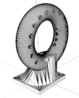
The first print of the lathe parts during the night was successful. The image below is a screenshot of SketchUp showing the imported geometry from the complete lathe .stl file from
http://www.thingiverse.com/thing:12472


The part that I decided to print first is highlighted in blue above, and shown in its own file below.

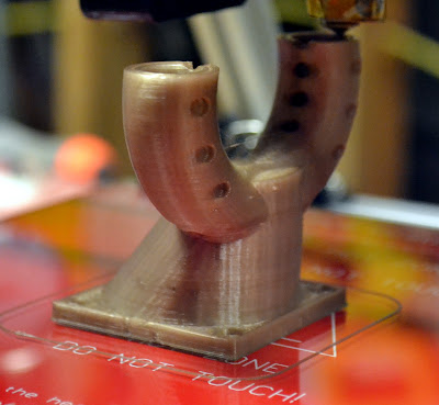
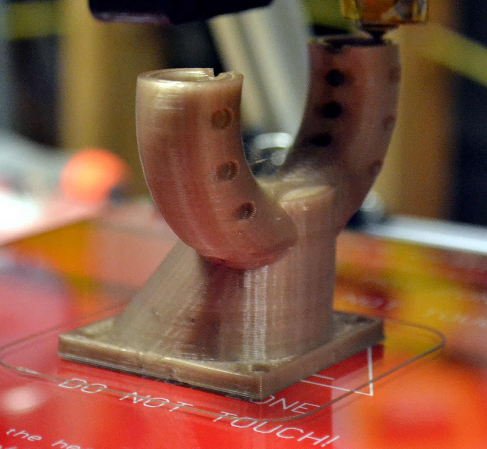
I exported the .stl from this single file and sliced it using Slic3r, using 0.7 as an infill factor, 3 perimeters and 3 solid layers, and it took my printer right at 4 hours to make the piece shown below.

My MendelMax 1.5 is performing well, but I am starting to see an issue in the last few prints that I had not seen before. There appears to be a slight gap between traces of plastic on the same layer, and the infill even on the outer "solid" layers appears to be thin. See the next two images of the print shown above.

These top layers should be solid and there should be no open holes, especially not as large as the ones that appeared here on the inside of the print:

Except for the hole in the middle with the nut capture geometry and the two holes spaced out at 90 degrees from the center, the surfaces shown above should be completely solid. I even saw some delamination of some of the bottom layer traces:

Zoomed in here:

I definitely have seen signs that my PLA has absorbed too much moisture--blobbing, small puffs of smoke from the water buildup, even what looks like some water oozing out of the nozzle when the machine is warming up and I feed filament through to make sure it's primed. It has been open sitting on a spool holder on top of my machine for right at three weeks now. I think moisture absorption is causing the traces to be undersized or varying in size.
For now I have fudged the filament diameter setting lower to force a little more material out, and will wait until I get my next batch of PLA in before I do any more investigation. At the rate I'm burning through filament on this lathe project, the next spool of PLA will need to be here about another day from now anyway . . . :)
D
Printing A Lathe
I was working on a design for a printable Stirling engine based on the Miser from Jerry Howell (http://www.jerry-howell.com/Miser.html -- there are several other beautiful Stirling engine kits on his site) last weekend, and I realized that there are a few parts that will have to be turned on a lathe. I started thinking about how to get my hands on a lathe again, and then I remembered that I had seen some printable lathes on Thingiverse . . .
Right now I'm printing the first of many, many parts that will be needed for a printable lathe similar to the one shown here http://www.thingiverse.com/thing:9242 and here:
The version I'm printing is found here http://www.thingiverse.com/thing:12472 This is a derivative of Sublime's lathe shown in the video above, and it is a version recommended by Sublime I think because of the geometry of the gears. I expect this project to take several days if not a couple of weeks. It will require several tens of hours of printing time alone. I hope to print several parts each night, several more during the day, and then a third shift when I get home from work each day. We'll see how it goes.
I'm suspicious of how much precision I will be able to get out of a 3D printed lathe, but the videos and discussions online are promising. If nothing else, I know I will learn a lot more about lathes and machine design in general by printing one out piece by piece and putting it together.
The original designer goes by the name Sublime online, and his blog is over at http://geometricobjectdepositiontool.blogspot.com/ Considering what he's been able to create using mostly printed plastic parts, this is a pretty incredible design. He also has several other impressive projects going, including his own version of a 3D printer. Please check out his work. Much respect.
Pictures/videos to come as the printing and building proceeds . . .
D
Thursday, September 6, 2012
Reality Somewhat Bites
Just a quick note to express my frustration at having to work enough over the last couple of days that I haven't been able to get back to the basement to print anything.
Tomorrow is Friday though, and in all seriousness I am glad to have a good job. I will make up he lost time this weekend I hope.
D
Monday, September 3, 2012
A Bridge Too Far
I've been trying to print bridges most of this Labor Day afternoon. Not because I've been having trouble with bridges (only because I haven't printed any), but because I suspect that being able to print good bridges will also mean that I have flushed out some of the other issues with my prints.
I've been printing the bridge calibration object "20mm-hollow-box.stl" found on the http://reprap.org/wiki/Calibration page. The first several attempts looked like this:

I tried adjusting the "Bridges (mm/s)" speed in Slic3r to improve the result. I ended up going from 60 mm/s to 100 mm/s, but really did not see any improvement.
I could see that the walls of the box were flexing when the printer was trying to make the bridge on top, so I suspected that the material was not cooling sufficiently (Note: I do not think that the Slic3r setting for "Slow down if layer print time is below (approximate seconds):" is working, since the layers that print only the walls of the box certainly were printing in less than 15 seconds). So I decided to print four of the boxes at once, to give each one a chance to cool more, and the results were a little improved:

Yet another case for adding a duct and cooling fan . . .
I decided to try and increase the bridge speed setting in Slic3r even more, so I bumped it up to 150 mm/s. This didn't show any noticeable improvement either, and I started to realize that the top speed on the bridges seemed to be the same whether I was at 60 mm/s, 100 mm/s, or 150 mm/s.
I remembered there is an acceleration setting in the Marlin firmware, and with some quick calculations I decided that the acceleration was not allowing the bridge speed to reach its max value, so increasing the max bridge speed was no help.
My acceleration speed (search for "DEFAULT_ACCELERATION" in the Marlin configuration.h file) was at 1000, so I increased it to 2000 and the print looked basically the same as before.

Next I increased it to 5000, and the machine started missing steps--especially on the Y axis--and ended up trying to start printing the bridges in thin air, which didn't work well:

I decided to go lower than where I started, to understand if the bridge speed was as critical as I had thought at the beginning of this exercise, and at 500 mm/s (1/2 of the original setting) I saw no real degradation.

Which again leads me back to a cooling fan . . .
So I decided to get serious about a fan duct. I picked one out on Thingiverse and checked the IRC channel at http://reprap.org/wiki/IRC (this is a great place to go for advice, btw), and decided to go for it.
The part I selected from Thingiverse is the 40 mm fan duct ring at http://www.thingiverse.com/thing:23960 The print went well overall, and looked really nice from the outside. I had to turn a fan on it due to some curling up on the edges when the overhangs started to form. Here are a couple of images taken as it was printing:

I had to leave the basement with about 30 minutes left on the print, but when I was able to come back down I was very relieved to see that it had completed successfully. I did notice that the ring portion that I expected to be circular was a little oblong. Not a good sign. Also, when I held it up to a 40 mm fan to check if the holes aligned, they did not . . .
I imported the .stl file into Sketchup using the STL Importer by Jim Foltz:

And measured the length and width of the base, but the scale of the imported .stl must have been off in Sketchup. I realized that the square base was likely supposed to be 40 mm square so that it would be flush with the outline of a 40 mm fan housing. Anyway, the base of my print measures 44.5 mm square, off by a good 10%.
Seems like I would have calibrated the X and Y axis movement distances before now, doesn't it? Well at least I know what I'm doing next . . .
D
Sunday, September 2, 2012
Today's Prints
This morning I printed the bottle opener from here http://www.thingiverse.com/thing:6188 and here http://www.thingiverse.com/thing:1842

Unfortunately the bottom of the print warped, and there was deformation in the lower part of the print (print is shown upside-down in the image below).

Not sure exactly what I need to do to keep that from happening, but a cooling fan and better temperature settings either in the extruder or on my heated build plate would certainly help. One task I've yet to complete is finishing the Slic3r calibration tutorial over at RichRap's blog http://richrap.blogspot.com/2012/01/slic3r-is-nicer-part-1-settings-and.html I'm guessing there are a few things in there that will help as well.
Undeterred (or too stupid to know better), I decided to try and print the ball and socket pieces to the helping hands prints I had started a few nights ago. There were definitely some issues during the print, but I thought things were going well.
I realized that out of the 12 pieces I was printing (4 copies on X by 3 copies on Y), 6 had serious issues. The bottom of the ball and sockets print in four separate pieces up until the end of the slots that allow the sockets to flex around the ball they're attached to. On 6 of the pieces, one of the four tabs had fallen down.
Luckily, the print was able to mostly recover, and things were looking good again until the print got to the levels where the balls begin to form. As the balls grew out larger and larger with each layer, I began to see the edges of the balls curl upwards. The printer was handling this OK, but the nozzle kept hitting the pieces when it traveled back to the start of each layer. I didn't realize that this was making the printer miss steps, and the pieces ended up with a pretty bad shift to one side about 1/2 the way up the balls.
I've posted a video of the print below. Even though the parts aren't perfect, it's still a lot of fun just to sit and watch the printer work.
Hopefully tomorrow and Monday I will be able to complete more calibration exercises and improve the quality a little more.
D
Subscribe to:
Posts (Atom)