Friday, August 31, 2012

Heated Bed Success

The heated bed was delivered today, and when I got home from work I began installing it on my MendelMax.  Had to take a break for several hours but then got back down here around 10:30 and after a couple of hours I have it installed and am printing parts--with very good first layer results!!!

The MK2 heated build plate (HBP) is a lot smaller than the available printing area on the MendelMax, but I wasn't concerned with that for now.  I just wanted a dependable, reusable solution for getting the parts to stick correctly.  When I need to print larger parts, I will have to come up with a solution that restores the print area to its original capacity, but for now I'm thinking quality over quantity.


I wasn't sure what to use to space the HBP off of my composite support panel.  I had to go over to my parents' house this afternoon, and while I was there I picked up my glass cutter because I knew I needed to cut the piece of glass that I use as a printing surface to a smaller size so that it would fit the HBP.

When I grabbed the glass cutter, I also decided to bring home a small plastic cabinet that had drawers of various screws, drill bits, and other hardware left over from my previous life of circuit board and robotics work.  When I got back here and started working on the HBP again, I saw that there were 1/2" aluminum spacers in one of the drawers--perfect for spacing the HBP off of the composite panel.


I placed a washer on top and underneath the spacers, and the end result is clean and should keep the HBP far enough away from the composite to prevent any excessive heating and off-gassing from the resin (I'm not sure if that's even a legitimate concern at the temperatures we're dealing with, but it sounds reasonable).


I soldered wire onto the board for pushing current through the copper to generate heat, and soldered lead wires onto the thermistor that came with the HBP from reprapdiscount.com.  I connected the power wires to the D8 terminal block on the RAMPS, and connected the thermistor leads to the T1 position.  

The first time I ran Pronterface to try and get the HBP to heat up, it the LED's on the HBP were not illuminating.  I figured there was something wrong with a firmware setting, so I browsed through the configuration.h file on the Marlin firmware and, sure enough, I needed to change a setting for the type of heat sensor from "0" to "1" in the firmware, to match the thermistor I am using.  (If you have similar issues and want more detail on what had to be changed and why, please let me know).


I'm satisfied with the end result for now--especially since I'm watching some very good looking prints take shape right now.  If the first layer sticks consistently using this new HBP setup, I'm in for a fun weekend of printing . . . 

D

Wednesday, August 29, 2012

Heated Bed is On Its Way

Today I was looking forward to the arrival of a heated bed for my MendelMax.  I have decided that it is my best hope for a consistently adhered first layer, and so I wanted to get one in and stop wasting time restarting prints each time my blue painter's tape failed me :)  Unfortunately, the FedEx package needed a signature release, so it will not be delivered until tomorrow.  

The heated bed that I ordered is the MK2:  http://reprap.org/wiki/PCB_Heatbed


I hope to install this tomorrow and try it out tomorrow night . . .

D

Tuesday, August 28, 2012

Helping Hands

I started to buy a set of "Helping Hands" today in a store, and then it occurred to me--I have a 3D printer!  So just now I looked on Thingiverse and, sure enough, there is a Helping Hands thing here:

http://www.thingiverse.com/thing:14012

And the more basic ball and socket pieces are here:

http://www.thingiverse.com/thing:5578


I think I will print the ball and socket pieces and put them on a block of wood for a quick but useful set of helping hands.  I have some alligator clips to stick in the ends to complete the build.

This would have been very useful when I was building the MendelMax in the first place.  Used to own a set but I think I left them at a friend's house.  No worries now that I can print out physical objects.  :)

D

Sunday, August 26, 2012

Planetary Gears Print

A forum member suggested using a fan and setting the temperature lower to improve the 50 mm tower print, and both methods yielded improved results.  I still don't have a good way to mount a fan and properly duct the airflow, I was just holding it in my hand and directing it toward the print.

I had a lot of trouble getting good adhesion on the first layer of the prints this afternoon.  I'm printing with PLA and had been getting decent performance from blue painter's tape over a piece of glass (not heated), but it took me a while today to get things to stick well, and I ended up wasting a lot of time on that.  In the end, I think it was a matter of getting the correct Z-axis homing position so that the first layer got smushed onto the tape.

Once the first layer was sticking again and I had completed a second 50 mm tower, I was getting tired of just printing calibration objects.  So I found these planetary gears on Thingiverse: http://www.thingiverse.com/thing:23030

I knew it was ambitious, but I decided to print them out, and here is a movie of my MendelMax 1.5 in action:


I just sat there for minutes staring at the machine while it ripped back and forth printing out gears, nuts, screws, and knurled (yes, knurled) pieces :) .  Here are the parts after they were done (and a few strings were trimmed off--not many though, thankfully).


A couple of pieces that were taller and had a smaller base toppled over during the print, leaving me a few pieces short on assembly:


But hey, you're not much of an engineer if you can't adapt to adversity, so I was able to grab a M8 bolt and finish the assembly.


At this point I feel like the printer is able to print well enough to make useful, functioning components.  Time to bone up on some of the open source CAD software out there and start designing my own parts to print.  I say open source because even though I have several years of ProE and NX/Unigraphics experience I do not want to spare several months of my salary to buy a license for either one :)

Of course, there is Google Sketchup with a .stl export plugin . . .

D

50 mm Tower Calibration Print

Yesterday I was able to print out the 0.5 mm wall thickness calibration objects after correcting my extruder steps (found out that setting was way off thanks to the great calibration tutorial from RichRap at  http://richrap.blogspot.co.uk/2012/01/slic3r-is-nicer-part-1-settings-and.html).  The look of the 0.5 mm wall thickness is great now, and the wall thickness is right around 0.5 mm, so I decided to move on to the next calibration prints.

One of the prints is the 50 mm tower (file name "50mm-tower.stl).  It's supposed to help determine temperature settings, and is basically a 2" tall tower about 1 cm square, printed with 100% infill all the way up.  


This is what my first attempt looks like.  The calibration page in the RepRap wiki (http://reprap.org/wiki/Calibration) says "If it looks like a blob, turn down all the temps by 5 degrees until you get something good."  I think my result isn't great, but also not quite a blob, so I'm going to post the picture to the forum on RepRap.org and see if I can get some feedback on how bad or good this is, and what I need to do to improve it.

D

Saturday, August 25, 2012

Extruder Setting Error

I was going to post a picture of my latest calibration print and some questions about the issues I was seeing in the corners to the forums over at  http://forums.reprap.org/  I decided to search to see if the solution was already in the forums, and I came across a great forum and calibration tutorial that immediately showed me that my extruder settings were wrong.

Here is the blog:  http://richrap.blogspot.co.at/

And here is the first of three pages explaining how to calibrate the settings in Slic3r and your firmware to improve your prints:  http://richrap.blogspot.co.at/2012/01/slic3r-is-nicer-part-1-settings-and.html

After doing the test for extrusion length using a piece of tape on the filament, I found that when I told my machine to extrude 50 mm of filament it really extruded more like 82 mm.  Awesome--I found something definitely wrong that I can fix to improve performance. 

So a quick change to the steps per mm setting in Marlin and I was ready to re-slice and print out the 0.5 mm calibration object again and enjoy vastly improved print quality.  I was looking at RichRap's blog and not really paying attention to the print, and then I looked over and saw that the print was probably 90% done but only about 50% of the height I expected--I had made the change to the steps per mm to the Z-axis instead of the extruder!

It's funny how the machine just doesn't care.  "Ok fool, you want to make the Z-axis move that way?  Fine.  Here's your piece of crap you wanted to print.  I did my best.  Enjoy."  :)

I corrected the setting to the Z-axis and made the change to the extruder movement, but then my son woke up and it was time to come upstairs for the morning.  When he goes down for his nap this afternoon I will be able to print again .  I'm excited to see how much this correction affects the prints . . . 

D

Calibration Continues

I kept printing the 0.5mm-thin-wall.stl file to try and get it dialed in, and I kept seeing a really smooth finish on the bottom 1/3 or so of the part but then it seemed to get off.  After printing a few dozen of these at different times and with different adjustments to the settings, I started realizing that the prints started to deteriorate at about the same height each time, somewhere around layer 13 or so.


I began to think that maybe there was something in the Slic3r or Marlin settings that was leading to a change in parameters around 1/3 of the way up the print, but after looking through the config file for Marlin and the Slic3r settings I could not find anything that I could reasonably expect to cause the problem.

I have thought all along that I have been having some issues because the material is not cooling quickly enough, especially in areas where I'm laying down a lot of material.  I saw in Slic3r that you can have it slice  multiple copies of the same object:


I thought this was a good way to test the theory that more cooling time would help with the issue shown above, since each of the two objects would get twice as much time as normal to cool between layers.  I tried printing out the two objects at once and, viola:


The two on the left were printed one at a time, and show the decrease in quality about 1/3 of the way up the print.  The two on the right were printed together side by side, and the quality of the finish on the walls continued all the way to the top in most places. 

There certainly must be other factors at work, but I think it's safe to say that more time for cooling (and maybe active cooling) is something I need to improve print quality with my current settings.  

I'm definitely still having issues on the corners and I think where the extruder retracts for the Z-axis movement and then starts extruding again.  Looking at the image below, the corners get a little ugly the higher you go on the part, and I can also see that the last corner that gets printed (back left in the image below) is clearly the best quality of the four.  


In fact, this back left corner is really, really nice.  If I can repeat the results above for multiple parts I will probably try adjusting the extruder settings.  In fact, I will post these to the forum at http://forums.reprap.org/ and see what the experts think--probably can save me a lot of time playing around on my own.


If anyone sees issues or has tips or advice, PLEASE comment and let me know!  I only have about a week of experience on the machine, so I still have a lot to learn.  Thanks!!

D

Thursday, August 23, 2012

Is Kapton Tape to Blame?

. . . I think I know why the parts I printed last night stared to warp and separate from the build platform when the previous ones did not--I think it was the Kapton tape.

Up until last night I had been printing on bare glass, but that seemed to not be working well anymore, so I added the tape to the top surface.  I think the tape is enough of an insulator to keep the part warm a little longer, and the parts are warping as they cool as a result.

I'm definitely planning to install a cooling fan to see if that makes the issue go away.  Fingers crossed.

D

One Problem Solved . . . On to the Next One

I had been printing for two days and everything was moving right along, then last night when I tried to print the last two spool holder parts the printer started acting strange.  After a few layers, the positioning would be off and it would start to print too far towards zero on the X-axis.

I did not have enough time last night to find out what the cause was, so I took a close look today and finally found that the pulley on the X-axis motor did not have its set screw tightened down . . .  That would do it, for sure.

With that problem solved I was able to then print out the last two spool holder parts that I needed, and now my plastic spool is sitting on top of the machine rather than off to the side.  The filament can feed straight down to the extruder, and there should be no issue with twisting or tangling like there was when the spool was just sitting on the workbench beside the machine.


I also was having issues tonight getting the PLA to stick to the glass plate.  The first couple of days I had no issues with adhesion, then last night and tonight I wasn't able to get an entire first layer to stick to the bare glass.  

I ended up adding Kapton tape to the glass surface.  Right away I saw a vast improvement in the adhesion of the first layer to the build surface.  However, the spool holders I printed both warped slightly and pulled off of the Kapton tape on one end.  

One way to address this would be to find something that the PLA adheres to better, but from what I can tell by reading online, the PLA should not show a lot of warping, and Kapton tape is one of the most popular means for improving adhesion.  

To really solve the problem, I think I need to install a fan that blows on the material after it comes out of the nozzle.  I've seen some pieces on Thingiverse.com that might work.  I also need to spend some time completing the calibration prints, so the fan may have to wait.  We'll see.

D

Tuesday, August 21, 2012

First Attempt at Printing Real Parts

I have not finished all of the calibration steps listed on the RepRap.org Wiki's Calibration page, but I couldn't wait any longer to print "real" parts.  Also, I really wanted a spool holder.  The MendelMax 1.5 printed parts kit that I ordered and used to build my printer did not include a spool holder, and I was beginning to worry that the way the filament was feeding up and into the extruder from the spool sitting on the table beside the printer might cause some issues.

The spool holder I decided to print was this design from Thingiverse:  http://www.thingiverse.com/thing:16586

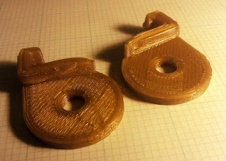
Everything looked great on the larger, flat, lower part of the print.  When the printer got to the small portions that stick up off of the bed and form the clips that latch over the corner of the extrusion, things got a little hairy.  I think I will be able to use the parts, but I am pretty sure I need a cooling fan to help material solidify when the printer is working on small parts that are close together.

Here's a video of the early part of the print:


And this is the end result.  Note the deformation on the upper portion of the parts.


Need to print two more of these to form the spool holder, then I think it's time to mount a fan to the extruder/hotend carriage.

D

Calibration Print Video and Layer Height Adjustments

I wanted to post a video of the printer making something, albeit something that still needs a lot of work.  Here is a video of my MendelMax 1.5 printing the 0.5mm-thin-wall.stl file from the calibration page of the RepRap.org Wiki, located here:  http://reprap.org/wiki/Calibration


After this print I remembered that I needed to try and tighten the timing belt on the X-axis.  I did that and printed another copy of the same object, and the results were "interesting".

On some of the passes around the print, when the extruder reversed and the printer moved up in the Z-axis, the PLA would not begin flowing out of the nozzle again until the printer had moved down the rest of that side of the print and started to move along the adjacent wall.  The last two walls that the printer formed looked very good, but something appeared to be going on with the extruder reverse setting or flow rate or something along those lines.


Next I decided to adjust some of the layer height settings, since that is what this particular .stl file is supposed to help you calibrate.  Slic3r was at 0.4mm layer height by default.  I tried 0.5mm and got a print with much more wavy walls.  Then I tried 0.3mm . . . wow!  I'm sure there are lots of other variables at play, but two of the four walls were almost perfect.  Brings a smile to my face . . . :)


So, for now, I choose a 0.3mm layer height.

On to more printing!!

D


Monday, August 20, 2012

It's Alive!!!

Completed the last of the build on my MendelMax 1.5 today, and actually got it to squirt out plastic.  Here is a picture of the printer itself:


The pic below shows my first four attempts (in order from left to right) at the 0.5mm-thin-wall.stl calibration part:


Some info on the four attempts:

1.  Hotend was nowhere near the build platform surface (I was just trying to get it to move and make PLA come out :) )
2.  I think the extruder had not pushed the filament far enough into the hotend before the printing started, so the print was doomed from the start.  I was happy to see a square-like shape though.
3.  Better still, I think a little PLA was gooped up on the nozzle at the beginning, but not sure.
4.  Just another attempt with no major adjustments.

Here is a closeup of the fourth print above:


When I saw the bottom several layers on this one side I just smiled :)  Oooh, the possibilities!!!

It took me a month and a half of working nights and weekends to get to this point, but I am so excited to finally be making something.  I can't say enough about the amazing, dedicated, talented people who have made RepRap's a reality, and made 3D printing so accessible.  The printer hardware (Prusa, Mendel, MendelMax, etc.), electronics (RAMPS in my case), and software (using Slic3r with Pronterface, Marlin firmware) are just incredible.  I hope I can give back to the community as I keep learning and making!!

D