Wednesday, November 28, 2012

Printing Accurate Holes

So in addition to the printed lathe I have been working on a few other designs or ideas, and I thought one of them is worth sharing here on my 3D printing blog.

For the purpose of one new design, I need to control a brushless DC motor, and to read the speed of that motor (RPM).  In order to test out my method for control of the motor and measuring the speed of rotation, I needed to create a test fixture that would allow me to collect data and observe and improve my methods for control and measurement.  I designed a basic fixture shown below, taking advantage of the capabilities of my 3D printer to make the fixture accurate and easy to assemble:

Simple Test Fixture for Brushless Motor Control

The reason I wanted to share this fixture design is the odd shape to the left side of the picture with 10 holes in it.  In the fixture, I need to accurately print holes that are both 1/4" and 8mm in diameter.  Actually, I need to print pieces that have holes the correct size for a press fit of both 1/4" and 8mm steel rod.

Since I am making the parts on a 3D printer, I do not have to take a lot of time trying to get the hole diameters exact--I can just print out a range of hole sizes in a test part and then try out the fit.  Once I've done that, it's easy to adjust the holes in the pieces that make up the fixture accordingly, for a perfect fit in the final assembly.  

The piece with 10 holes in it contains holes that are larger or smaller by about 0.004", allowing me to zero in on the correct size quickly.  After a couple of quick prints and test fits, I can adjust the pieces that make up the test fixture, print, and assemble.

D

Friday, November 16, 2012

Printing A Lathe - Assembly Begins

In the previous post I talked about the 3-Jaw chuck, which I have had assembled for a couple of weeks now.  Beyond the assembly of the chuck I had not been able to work on the printed lathe project any more for some time, but am trying to get back to it this weekend.

A few weeks ago I did finish all of the prints required for the entire lathe, and I also ordered the smooth and threaded rod and bearings that I think I need to complete the rest of the assembly.  I decided to go with all metric hardware, including 8mm smooth rod and 8mm diameter, 1mm pitch threaded rod--to give a nice even 1mm of movement per rotation.

I knew most of my work designing parts will be in metric, and I have used mills and lathes set up for inches with graduation on the dials for metric in the past.  The problem is, that leads to an amount of movement per rotation that is some odd number of metric units, and trying to keep track of positions over several rotations of the dial gets to be very difficult.  1mm pitch means 1 rotation = 1mm of movement (or 2mm off the diameter of the turned piece if the tool advances 1mm towards the center of the piece).

Here's what I ordered from McMaster-Carr as far as smooth and threaded rod, in case anyone is interested (Note: this is not a full list of all components needed for the lathe, and I have not completed the assembly, so some of these items may have to be changed):

  • 98861A320   Metric Class 4.6 Plain Steel Threaded Rod, M8 Size, 1 Meter Length, 1.0 mm Pitch, Fine Thread -- $13.52
  • 91415A105  Metric Zinc-Plated Steel Fine Thread Hex Nut, Class 8, M8 Screw Size, 1MM Pitch, 13MM W, 6.5MM H, packs of 100 -- $9.27
  • 88625K67O1 Tool Steel Tight-Tolerance Rod, 8 mm Diameter, 3' Length -- $5.59 (2 pcs. ordered, $11.18 total)

I went on a tangent this morning and printed a small part for a friend, just to feel cool about having a 3D printer:

Duplo to Brio Converter Brick

It's a piece to convert from Duplo blocks to Brio toy train track pieces.  The design is from Thingiverse here:  http://www.thingiverse.com/thing:14175  Turned out pretty well, but I have to get my hands on some blocks and train track pieces to see if it works.

Now back to very serious things like assembling my own printed lathe.

D

Printing A Lathe - 3-Jaw Chuck Assembled

First, I can't believe it's been about a month since my last post.  Work and life sure can get in the way of trying to take over the world . . .

Although I haven't worked on the assembly of the full lathe, I did manage to assemble the 3-jaw chuck:

3-Jaw Chuck from Sublime on GitHub

Here is an image of the parts that went into the assembly EXCEPT for 3 springs, 3 washers, and 3 pins (shown below):

Most of the 3-Jaw Chuck Components and Hardware

The 3 pins are the items highlighted in red below in this exploded view of the chuck from SketchUp:

3-Jaw Chuck Exploded View with Pins Highlighted

The assembled 3-jaw chuck is working OK, but the three pins that press against the back of the face of the chuck to lock the jaws in place are not holding well.  The instructions call for these three pins to be cut to length from smooth rod.  Since I had to cut the rod with a band saw (I obviously don't have a lathe or I would have used that), I was concerned that I would not get the three pieces to be the same length.  I knew I could print them to a very exact height, so that's what I did:

Printed Pins for 3-Jaw Chuck

At first, these seemed to be working fine, but I think that after some loads and stress have been applied the three small cylinders are binding in the holes and not imparting sufficient load against the back of the jaw face.  I think I need to go back and replace these with smooth rod.

I had to drill out a few of the holes based on the hardware I ended up using, and what drill size you need and how much of this is required will vary from one person to the next depending on the behavior of your printer and your choice of hardware.

Drilling Holes to Size

I also used a drill bit to clean up some strings and stray traces of plastic where the holes are counterbored on one side of the piece shown below.  When the piece prints these counterbores require basically printing a cone, and it came out messy for a few layers inside the hole.  Not a concern for the overall function of the chuck, however.

Cleaning out Counterbores

If you do not have access to a drill press or just want to make the hole sizes exact, I suggest printing out a small test part for a fit check and then updating the models as needed before slicing and printing the full part.  The nut traps in the jaw pieces were too large for what I needed, so I did something similar there and reprinted the jaws.  No sweat!

On to the rest of the assembly . . .

D


Tuesday, October 16, 2012

Printing A Lathe - Files and Information

I received a request for the Mini Lathe plate files.  I've copied them to my Google Drive and have posted the info and links below.  In fact, I think I should list once again where I got the designs from in the first place.

The Mini Lathe I'm printing is on Thingiverse.  The title of the design is Mini printable lathe V2 + Chuck - OpenSCAD version by Daid, and the link to the Thingiverse page is here:  http://www.thingiverse.com/thing:12472

The 3-Jaw Chuck I'm printing is from Sublime, and it is hosted on GitHub here:  https://github.com/Intrinsically-Sublime/Longworth-chuck

I downloaded the assemble.scad.stl file from the lathe page on Thingiverse and the Three_jaw_chuck.stl file from GitHub, and imported the solid bodies into SketchUp (deleting the chuck that came with the lathe_assembly_.stl and replacing it with the 3-jaw chuck from GitHub), and this is how the full assembly looks in SketchUp:

Lathe Assembly from Daid with 3-Jaw Chuck From Sublime

I then divided the parts up into plates that fit into a 18cm x 13cm build area (for several not so great reasons this was my maximum build area at the time).  It took three plates to cover the parts for the 3-Jaw chuck, and five plates for the lathe itself.  I did include extra copies of several of the gears and smaller parts where there was open space (if the printer is going to run overnight or during work, might as well have it make replacement parts).

The five lathe .stl plate files look like this:

Lathe Print Plate 1 of 5

Lathe Print Plate 2 of 5

Lathe Print Plate 3 of 5

Lathe Print Plate 4 of 5

Lathe Print Plate 5 of 5
 
The SketchUp and .stl files can be downloaded here:  https://docs.google.com/folder/d/0BzlyGd7meNzeWmcyUVpOVENyUTA/edit

Two of the parts for the 3-jaw chuck did not print properly.  After looking at the .stl files in netfabb, it appears that there were some issues with some of the surfaces.  I am going back to reconstruct/fix those in SketchUp now.  Once I have those corrected, I will try to upload the plates I constructed to print the chuck as well.

After printing those last couple of parts it's on to assembly :)

D

Tuesday, October 9, 2012

Printing A Lathe - Only 2 . . . 1 . . . 0 Plates To Go!

At the time of the post last night I had completed 3 of the 5 mini lathe print plates, and the printer was working on a fourth.  This morning I was greeted with a print bed full of good parts:

Plate 3 of 5 for Mini Lathe Print

And a closeup:

Plate 3 of 5 for Mini Lathe Print, Detail

What's more, these parts popped off of the glass relatively easily.  To prep the glass for the previous plate (where the parts had adhered almost too well) I had applied the diluted PVA mixture to the glass and used a fan to dry it, and the glass had set overnight before I printed.  

For the parts shown above (and a few prints since then), I applied the diluted PVA mixture to the glass while it was sitting on the heated build plate and warming up to the target 85 C or so that I've been using.  Basically as soon as the coating dried I started printing.

For a few prints now that strategy has resulted in parts that stuck well during printing but that also popped off pretty easily.  I may have ironed out the last wrinkle in my method for using diluted PVA to get PLA to adhere.

So that left only plate 4 of 5 to print.  I took about 15 minutes this morning to get it started before I headed to work, confident that using diluted PVA on the heated glass was going to perform once more, and it did!  Here are the prints from the last plate:

Plate 4 of 5 for Mini Lathe Print

You can see in the picture that there are some issues with the holes in the large part in the lower right corner. It looked like the printer had tried to bridge across the holes and failed.  Going back and looking at the G-code viewer in Pronterface, that is in fact what happened.  

For some reason, Slic3r put a single layer over the top of the holes on that surface of the one large part, and I did not catch that until after I saw the completed print.  Not a big issue in this case, but another reminder to review the sliced models and compare them to the .stl's or the geometry of the model you are printing from.

Failed Bridge on Top Layer of Large Part

Except for two pieces that I need to reprint for the 3-jaw chuck, I now have everything printed out for the mini lathe.  Next step is to assemble the various vitamins (nuts, threaded rod, smooth rod, bearings, screws, etc.) and get down to assembly.  Still lots of work to do, but I decided to take a break from the lathe for tonight's overnight print and make something that I could put on my desk at work and show off (hopefully :) ).  Right now the printer is working on this spiral cup from MakeALot over on Thingiverse:  http://www.thingiverse.com/thing:6917

Spiral Cup from MakeALot via Thingiverse.com

So far so good on the first few layers, interested to see what greets me in the morning . . . 

D

Printing A Lathe - Only 3 Plates To Go

So, I did finally have success with the blue PLA.  I ended up using PVA glue (Elmer's Glue-All) diluted 1:8 in water on a piece of glass over a heated bed (see the previous post).  When I got up this morning plate 2 of 5 had completed printing, and seeing finished parts out of the blue PLA was very satisfying.

Plate 2 of 5 in the Mini Lathe Build

Completed Print of Plate 2 of 5

The parts were difficult to remove from the glass covered in PVA glue.  I ended up using a metal wedge I had with a razor edge (an old piece of lab equipment, I think for slicing thin layers of tissue) and was able to pry them off without a huge amount of effort.  It was not ideal though, and I think I would have had more success heating the bed and glass back up to 85 C or so before trying to pry the parts loose.  I will try that with the next print.

Here is a pic from a better camera (the image above was from my Galaxy Note) showing the blue parts from last night's print.  The blue PLA does look very cool (blue is my favorite color, so that helps).  The gold is also nice, but after a couple of months I was starting to get tired of it.  I have a spool of green still in the box that I haven't even opened yet.

Plate 2 of 5 of Mini Lathe Print in Blue PLA

Plate 4 of 5 is now printing (saving 3 of 5 for last I guess), and it also appears to be adhering well.  Here are a couple of shots of the first layer perimeters going down.

Plate 4 of 5 of Mini Lathe Print, Bottom Layer


Plate 4 of 5 of Mini Lathe Print, Bottom Layer Image 2

As you can see, I'm really squishing the first layer of plastic onto the glass plate.  The small flange that this forms around the bottom of the part does not seem like a big issue for these parts, so I'll take that small imperfection in order to be sure that nothing is going to come loose during the print.

I'm going to let the plate 4 print run overnight, and I have another piece of glass waiting to place on the printer tomorrow morning to start plate 3 of 5--the last plate to print--before I head to work.  It is so satisfying to be back where I can start a print and let it run without worrying about parts coming loose again. Really makes all the difference in the world in terms of output, since I can only spend a couple of hours at a time actually monitoring the printer.

One other note about using the PVA mixture--it did leave a milky white film and some white material on the bottom of the parts.  I first tried a little rubbing alcohol to see if I could wipe it off, then decided to try a small torch for some heat.  That worked like a charm, and I plan to record and post a video showing the torch making the white film disappear the next time I use this method.

Overall, the PVA seems to be an acceptable solution for getting the parts to stick well going forward.  Removal of the parts from the glass after printing is the only thing I'm not happy about for now, but I will try to re-warm the plate and see what happens.

As I type the current print has finished several layers and all seems well.  Time for some sleep while my MendelMax works on through the night . . .

D

Monday, October 8, 2012

I'm Back . . . I Think

Just a quick post to say that I'm seeing good results with a 1:8 PVA:Water mixture on top of heated glass with the infamous (if only in my own mind) blue PLA.  I'm confident enough in what I've seen on the first three layers to let the print go for the next four hours while I sleep, and hopefully I will wake up to the first complete parts I've seen come off the printer in somewhere around a month!

More tomorrow night . . .

D

Sunday, September 30, 2012

PVA for PLA

I don't have time to get to my printer for the next week or so, but as soon as I can get back I'm definitely trying the diluted PVA on top of glass to get the PLA to stick.

I was having lunch with a friend Friday, whining about my problems getting the blue PLA to adhere, and he said (paraphrasing here), "Isn't there some kind of glue or coating you can put down on the surface to get it to stick?"  Doh!!  Suddenly all the posts I had read through that talk about using a PVA and water mixture seemed much more important, and I couldn't wait to get back to the forums and blogs and find out how to make my own dilutions and get back to printing.

I think I had dismissed those methods before because my experience with the gold PLA on glass over a HBP had been so positive.  The thought of having to do some secondary operation and paint on a coating of some type seemed like an unnecessary extra amount of work, so I had put those methods out of my mind while I tried to find the right combination of extruder and HBP temperatures to get the blue PLA to adhere.  After a few weeks of frustration, though, the idea of painting on a film of diluted PLA seems like a very small price to pay to get the new spool of PLA to stick without problems.

I picked up some PVA glue (Elmer's) at Wal-Mart a couple of days ago.  I went with the classic tube of white glue with the orange top (http://www.elmers.com/product/detail/E1322?filterPath=school).  They also were selling a spray-on product that seemed interesting (http://www.elmers.com/product/detail/E422?filterPath=craft).  I'm curious if anyone has tried this, since spraying on a coating of glue could be a very quick and easy way to prep the glass surface.

I've decided to first try a dilution of 1:8 PVA:water on a cooled glass surface.  I've seen posts about mixtures stronger than that resulting in the parts not coming off of the glass (without taking some of the glass with them, at least):  http://forums.reprap.org/read.php?262,141761,141761  I've also seen posts suggesting that using this ratio on a heated glass plate works well:  http://richrap.blogspot.com.au/2012/06/more-scrap-art-gearboxes-and-panelmax.html

I'm a little worried that the piece of glass I have is not very tough.  I got it out of a flatbed scanner that I was throwing away.  I will try the cooled glass coated in PVA mixture, and if that doesn't work I will first try to thicken the mixture.  If that still doesn't work I will use the coating over a heated build surface.  Either way, I have a plan with potential for success, and that's really all I need to stay excited about the next steps :)

D


Friday, September 28, 2012

Tangled Up In Blue PLA

After several hours of frustration trying to get the blue PLA I ordered from Amazon to stick to the heated build plate, I finally have started to figure this stuff out.

To those of you who have been 3D printing for a while, my solution may seem obvious, but I want to briefly explain how I came to the correct settings.  Hopefully, by doing this I will both 1) save other people new to 3D printing and RepRap's wasted time and trouble, and 2) remind myself to look out for similar behavior in the future and avoid getting stuck on the same issue.

I had run out of gold PLA, which was the first spool of material that I had ordered and run through my MendelMax 1.5 printer.  Here is a link to the gold PLA I ordered:  Gold PLA 3mm from Amazon.com

I was very satisfied with this material's performance (I didn't know any better anyway, it was my first spool of material), and free 2-day shipping with Amazon Prime is just too tempting.  So for my next spool of material I also ordered from Amazon.com, except I got blue material, and it was from a different supplier:  Blue PLA 3mm from Amazon.com

Here is a picture of the material over my machine:

Spool of Blue PLA Over My Machine

I knew I would probably need to adjust the extrusion temperature when I switched materials, so when I started to print with the blue PLA I used a method described on the calibration page of the RepRap.org site. The basic idea is to set the extruder temperature lower and lower and keep trying to extrude material.  When you reach a temperature low enough that the extruder cannot push material through the nozzle, increase the temperature by 5 degrees and that's the temperature to use for printing.

This method did now work for me.

I had been printing the gold PLA at around 161 C.  I think I did arrive at that temperature using the method described above, and I had good results with this material (barring some times when I had other settings messed up) for several weeks.  When I tried the same method with the new spool of blue PLA, I came out with a temperature almost 10 degrees lower.  As mentioned in previous posts, though, at this temperature the material was not sticking to the build plate.

I tried increasing the temperature of the extruder and build plate, sometimes together, sometimes separately, and I tried a range of temperatures for each from as low to as high as I thought might be reasonable.  I think I tried a build plate temperature from 50 C up to 80 C, and a material temp as low as 150 C and as high as 175 C.  I also kept cleaning the glass over and over, wondering if that had something to do with the failures.

At one point I thought I had it, and a print got through the first layer of a large plate of parts for the lathe I'm printing, but when I came back down after the print had gone through maybe 10% of the second layer, I found that some of the pieces had lifted off and stuck to the hot end, and this is what I pulled out of the machine:

Melted Glob From Parts Not Adhering to Build Plate

That was about a week ago, after over a full week of trying with no success.  Finally, this past Tuesday on a whim I decided to jack the temperatures way up, to 181 C on the extruder and 73 C on the HBP.  I was shocked to see how well it worked--I felt like I had come back off the DL just in time for the playoffs.

The 181 C came from posts I had read online about printing PLA around these temperatures.  It seemed like I was printing the gold PLA at a relatively low temperature compared to other people, so I really thought my machine just wasn't reading the temperature correctly.  I guessed the 161 C I had been using for gold was probably more like 175 C in reality, so going much higher than that would be a bad idea.  Also, I had used the method described above to find the optimum temperature, and that lead me to believe that the blue PLA should be printed at a temperature something like 30 degrees cooler than the 181 C that eventually worked.

The 73 C temperature on the HBP wasn't such a stretch, since I had noticed that up until this temperature range it did seem to help with the issues I had been having.  It just couldn't solve them completely without me also adjusting the extruder temperature.
 
Right now I'm printing Plate 2 from the Lathe prints, and it seems to be doing great is mostly doing great but there was some trouble in a few areas on the first layer--I will see if it can recover.

Printing Lathe Parts with Blue PLA

Seeing it run at 181 C, it's hard to imagine why I did not know to go to this high of a temperature before.  I was going on what I thought was a proven way of calculating optimal extrusion temperature, and it ended up causing me to not try high enough temperatures.

I also have been cleaning the glass with 91% Isopropyl Alcohol (rubbing alcohol).  This seems to be working well, although I have no real way to separate its effect from the other variables that I have been working with.

So, in summary, if you are having trouble with adhesion of the first layer, you should try higher temperature to see if that allows the material to bond more strongly with the surface of the glass you're printing on.  In the end, there are lots of variables that come into play, but at least you will give yourself a chance to reach a temp that works, even if it seems far outside of the range suggested by using the min possible extrusion temperature + 5 degrees.

D

PS - Sorry for the title, just couldn't help myself . . .


Monday, September 24, 2012

The Blog Is Not Dead . . .

Since the last post about a week ago, I've spent almost all of my time outside of work and family responsibilities working on two new design ideas.  3D printing has taken a temporary back seat, but I did try to get back into the lathe printing this afternoon.

One other thing that has kept me from printing as much this week is the continued difficulty I'm having getting the blue PLA to adhere to the heated build plate.  I've tried varying the first layer height (adjusting the end stop), adjusting the extrusion and HBP temperatures, and this afternoon I decided to print the first layer extremely slow--I think the setting was a speed factor for the first layer of 0.05.  That's crawling.

This very slow speed seemed to be doing the trick, but when I came back down to check on the print a few of the parts had lifted and the extruder had a huge glob of blue PLA on it . . . so I'm still in the dark here.  When I get some time I will hit the forums and take a closer look at the issue, but for now I need to tackle these two new projects I have going and move them along.

What's great about it all is that the 3D printer will soon become key to the further development of the two projects, so it all comes together in the end.  I'm very frustrated with the blue PLA troubles, but I'm very excited to know that I can build prototypes and try out my ideas as soon as I finish the initial designs.  Awesome :)

D

Sunday, September 16, 2012

Printing A Lathe - Only 4 Plates To Go

After completing the first plate Friday night, I estimated by looking at the spool of PLA over the printer that I only had enough material left to complete plate 5, the smallest (in terms of material requirements) of the four remaining plates of parts.

Plate 5 From The Lathe Print

Unfortunately, the part in the lower left corner with 6 spokes and knobs on the ends did not slice correctly.  I didn't have enough time yesterday morning to figure out why, but when I was able to start working again yesterday afternoon I installed NetFabb Studio http://www.netfabb.com/ and loaded the .stl file that SketchUp exported to identify the problem.  

NetFabb looks like a very powerful piece of software, with capabilities for 3D part design, tool path creation, even 3D printer machine operation.  At this time, I'm only using it to analyze .stl files for errors or holes.

NetFabb clearly identified the issues with the .stl file by highlighting them in burgundy.  The screenshot below is of the part after I had made some changes to try and simplify it.

NetFabb Screenshot With Error Faces Highlighted

After more redesign is SketchUp, export, check in NetFabb, redesign in SketchUp, export, repeat, repeat, I finally got to a part that had no holes and would slice properly so that I could run the print.  I learned a lot about design elements and SketchUp behaviors to avoid so that the .stl comes out solid and will slice properly, but it did take up a large chunk of my available 3D printing time yesterday.

Last night I finally was able to restart printing plate 5.  I went upstairs while the bottom layer printed (since this can take 30 - 45 minutes with my settings and the size of these prints) and then came back down to turn on the fans around the machine for the remainder of the print.  I reached over to turn on a small portable fan I have sitting near the printer on my work bench, and the instant that I flipped the switch, the printer froze!

The hot end was still heating (the LED connected to the hot end output was flashing on and off), and the bed was turning on and off, but none of the motors were moving at all.  I tried to pause and resume the print in Pronterface, and after clicking on a few more movement commands with no response from the printer the software hung up.  I was out of time anyway, so I killed the software and the power to the printer and went back upstairs to sleep.

This morning I was very, very happy to see that I was able to connect to the printer again, so I new the board wasn't totally fried.  When I tried moving the motors, though, there was no response, and the software seemed to hang again.  I was able to turn the hot end and HBP on and off, so I decided that there was something wrong in the code dealing with motor movement, and Pronterface was looking for a response from the board and not getting it and thus becoming unresponsive itself.  I fired up the Arduino software, re-flashed Marlin onto the board, restarted Pronterface and bingo--all is again right with the world.

So now I'm printing plate 5 again, and have made it past the first layer and turning the fan on.  I was very scared when I flipped the switch, I have to admit.  I have no idea why turning on the fan messed with the board--it could have been a dirty spike in the power line, some strange EMI issue, or I could have bumped against the Arduino or RAMPS boards or cables and shorted something out.  

I know enough about controls and electronics to go ahead and file this problem into the "avoid" rather than "solve" category.  I hope to get a fan duct printed and installed at some point, and can then start using a much more focused, less powerful cooling fan that is turned on automatically by the software after the first layer.  That would mean a much more predictable and less severe change in power requirements, and I hopefully will not see this type of failure again.

D

Saturday, September 15, 2012

Printing A Lathe - Only 5 Plates To Go

I was able to get back to the MendelMax here in the basement late last night.  After completing the parts for the 3-Jaw chuck (see previous post), it was time to move on to the rest of the lathe parts.  I had already printed an upright before, but the quality was poor due to the trace width issues I was having at the time.

I started by loading the entire lathe assembly file (from here:  http://www.thingiverse.com/thing:12472) in SketchUp and identified the pieces I had already printed.  I am not using the 4-Jaw chuck shown in the assembly file below, but I went ahead and deleted those anyway since my 3-Jaw chuck was complete.


Then I drew a rectangle representing the maximum build area of my machine, and offset it in by 5mm for the offset of the skirt that Slic3r prints around the part.


I like leaving the gray face to give me something to position the components on when I'm building up the plate.  It's easy to delete at the end.

Once this area is defined, it's just a matter of arranging the components just as you would like them to print out.  One thing to note is that you want to change the individual parts to components (triple-click on a part to highlight all its edges and faces, right click --> Make Component).  This makes it very easy to move them around, and if you happen to position to components so that they interfere with each other, SketchUp does not try to combine the intersecting geometry.

Once I fill up the build area, I save the file as something like [descriptive file name]_Plate1.skp.  I then save it as the next plate [descriptive file name]_Plate2.skp, and go back and delete all of the parts that do not get printed in the first plate file.  What I'm left with is something like this--which is the first plate of 5 that I need to print to complete the lathe.


Then in the next plate file I start by deleting all of the parts that were printed in the first, move a new batch of components onto the build area, save it as the next plate, go back and delete the unneeded parts, and then repeat.  The five plates I ended up with for the lathe print are shown below.


One thing that I think is so cool every time I do this is that I can fill up the build area with extra copies of parts that I think might not print well or that might wear out or break over time and need to be replaced.  Since each plate takes around 7 or 8 hours to print, adding another gear or three and 1/2 an hour to the print time is hardly noticeable.  It's like getting spare parts for free . . .

I started the first plate last night around 1am, so it was still going when I got down here this morning.  Here is what the print looks like so far:


The print in the lower right corner of the image above with a cylinder and two rectangular pieces with two holes in each has one small issue.  The corners of the rectangular section closest to the front edge of the HBP have lifted off of the glass surface.  


None of the other parts have lifted, and I think I know why it happened to this particular part--this is directly in front of a fan that I have blowing on the build area.  I positioned the fan here because I knew there were two taller parts at this location (see the image of Plate 1 above), and I wanted to make sure each layer was cooling sufficiently when the total print area on each layer started to get small.  If the lift and warp on this particular part turns out to be a problem, I can always make another . . .

Hope to start the second plate printing just as soon as this first one finishes, so that I can get another two plates printed in the next 24 hours.  IF everything goes well, I can complete the print of the lathe parts before I leave for work on Monday.  

One thing that has to happen before that is a switch to a new color of PLA.  I'm almost through my first 1 kg spool of 3 mm filament . . . feels like some kind of a milestone.  I decided on blue for my next color.  Hopefully I can dial in the correct printing temperature for the new color quickly (from what I read the optimal extrusion temperature varies even from color to color) and keep right on printing . . . 

D

Thursday, September 13, 2012

Printing A Lathe - 3-Jaw Chuck

The print of the 3-Jaw Chuck that I started last night around midnight completed this morning after I had to leave for work.  Everything looks like it came out great.  This print was a plate full of chuck pieces, as shown here:


Here are a couple of shots of the parts actually printing:


When I got home tonight I turned everything off and had to leave the printed pieces on the printer and come upstairs, but it looked like there were no major issues.  During the print I had a lot of air blowing across the print to keep the parts from warping, especially where they were positioned close to each other.  I did notice some strings on the parts.  I think this can be caused by too much cooling/too low material temp.

Also, below is a shot of the first layer of one of my prints.


I've been setting the Z-axis end stop low enough to cause the first layer to be squished against the glass.  This leads to a slight lip on the bottom surface of the print, but to me that is well worth it to make sure that the parts don't come off of the HBP before the print is complete.


The last thing to share tonight is two videos of this large plate of items being printed.  Please see below and on YouTube.


This second video is very similar to the first, but the camera angle is shallower and the camera is much closer to the print.


Just a reminder, these components are for the 3-Jaw Lathe Chuck by Sublime, hosted on GitHub at:    https://github.com/Intrinsically-Sublime/Longworth-chuck  With this successful print, I now have completed all of the 3-Jaw chuck pieces.  Time to print out the rest of the lathe, order the "vitamins", and assemble.

D


Printing A Lathe - Restart

On Sunday the 9th I reported that I was going after the biggest single printing I had ever attempted, and hoped to be done with several more of the parts to the lathe that night.  I also noted that my trace lines seemed to be too thin, and that I suspected humidity in the PLA, or possibly some calibration error.  Well, a lot has happened since then.

Sunday evening I came down to find that the spool of PLA had fallen off of the spool holder on top of my MendelMax.  I have been using the "Minimalist Spool Holder for MendelMax" designed by Michael521 over at Thingiverse:  http://www.thingiverse.com/thing:16586  My prints for the parts for the spool holder were not that great, but they were functional, and the spool holder had been serving me well.  

During the long print Sunday afternoon, something happened to make the spool jump out of the spool holder (nothing holds it in other than gravity).  When I came to the basement about 5 hours into the 8 hour print I saw the spool of PLA perched precariously on the edge of the workbench behind the printer.  My best guess is that the extruder moved rapidly from one side of the machine to the other, causing the filament that was already unwound to push back against the bottom of the spool in just the right orientation to make the spool raise up and out of the holder instead of rotating.  

Whatever the cause, the print was still going and all I needed to do was place the spool back in its holder and sit back and wait for the print to complete.  Unfortunately, I somehow knocked one of the four spool holder pieces off of the top part of the frame, and it fell into the base area of the printer, underneath the build platform.  Just when I tried to reach down and retrieve this piece, the platform made a rapid move and pressed against my hand before I could get it out of the way.  I felt and heard the Y axis miss a half second's worth of steps.  

I watched the machine go on printing for several more seconds.  It was completely unaware of any problem, what with its naive, trusting, open loop view of the world around it . . .  but I knew that there was no way back.  The layers were misaligned, and the print was ruined.  

Such is life, so I decided it was a good time to check the calibration of my extruder steps per mm to see if I could correct the trace width issues I was seeing.  I printed out a single wall print a few times and measured the wall thickness vs. what the .stl file was measuring, and, sure enough, my steps per mm was way too low. This had been causing the printer to extrude far too little material, and the result was the thin traces and holes in the infill areas that I showed in the last couple of blog entries. 

With the extruder setting corrected I was ready to resume printing the parts to the lathe, but by that time Sunday night I couldn't muster the will to go on.  I needed to setup and prepare for the large print that I needed to restart, including finding a more dependable way to mount the spool of PLA.  I decided it was better to just go to bed.  

After a couple of nights away from the basement I was able to spend time back on the machine this afternoon and evening.  The first order of business was to find a new way of mounting the spool of PLA.  I had thought about printing out a new spool holder, but I knew that I just needed a way of positively securing the spool somewhere above the machine frame.  

The simplest (and ugliest) way I could think of was to drop a piece of plastic conduit from the ceiling.  I'm not one to stand on ceremony when it comes to solving problems, and in about 2.5 minutes from start to finish I had the spool mounted very securely in a location where it could feed the filament directly to the extruder, no matter how far the X carriage moved side-to-side:


Beautiful, no?  Thingiverse worthy?  I think so.  Problem is, to create a thing on Thingiverse you have to upload at least one file that is not an image.  I didn't model anything in CAD or write any code for this design--it was just pure, raw inspiration and innovation--so I guess the Thingiverse community will miss out on this particular design.  Every system has its flaws . . .

Before I started over printing the lathe parts with the corrected extrusion setting, I found on Sublime's GitHub page for the printable lathe that he used a 3-jaw chuck for his own lathe.  I decided that I would go for the 3-jaw chuck over the 4-jaw that I had started with, so I downloaded the .stl files for the 3-jaw chuck from here:  https://github.com/Intrinsically-Sublime/Longworth-chuck  Here is a view of the .stl file for this design:


I started by dividing the components into three plates (that was the fewest number of prints I could manage to arrange them into):

Plate 1

Plate 2

Plate 3

I numbered them from 1 to 3 in the order I am printing them, starting with the most simple and going to the most complex.  The third plate contains several extra copies of the cylindrical pins, chuck jaws, and planet gears.  I figured that since there was room for more copies on this plate I should make extras in case these parts wore out.  I also was thinking that by the time I got to Plate 3 I should have things pretty well dialed in, and adding the extra hour or so to an overnight print would go mostly unnoticed.

The first print of the single thin disc-like part came out well:


Definitely have enough width to the trace lines now to completely fill in the print:


In fact, if anything I overshot and might need to adjust things down a little.  Not planning to mess with that for now though, since it's not exactly "broke".

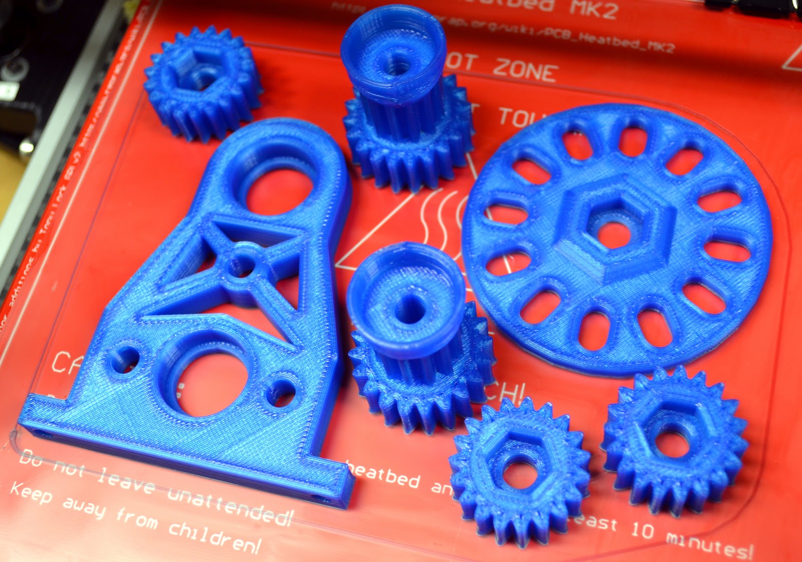
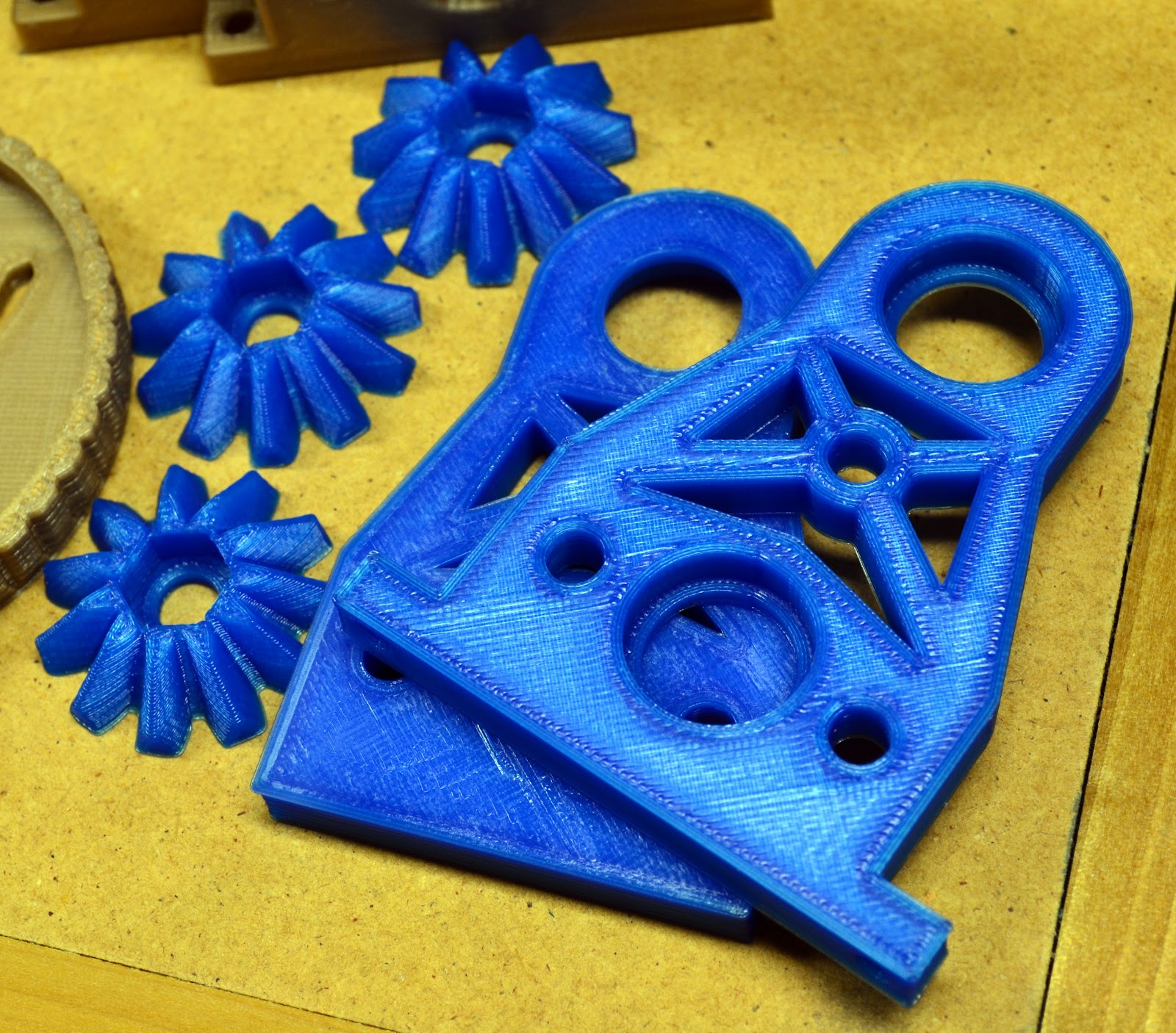
The first plate/part took about 35 minutes, and the second took about 4 1/2 hours.  Here are the results still on the heated build plate.  These also turned out well:


There was some slight distortion of the part in the area where the two pieces are closest together.  I'm betting that came from a lack of cooling, since they are in such close proximity to each other.  Before starting the massive print that is Plate 3, I decided to set up some fans blowing on the machine to try and keep this from happening again.  I have a lot of parts on that plate squeezed in close to each other, so I worry that without adding fans I will be asking for lots of warpage trouble.  

Fans are set up, bed is heated, and I'm about to get things going before I head off to bed.  Fingers crossed . . . if this print works I will be maybe 1/2 way through the lathe print.

D

P.S. -- Sorry for the long, drawn-out post, but I'm finding that the blog is very useful for going back and understanding when I did things.  I decided to try and record what went wrong with the large print on Sunday so that I do not make the same mistakes again.  Thanks for reading!!