Wednesday, November 28, 2012

Printing Accurate Holes

So in addition to the printed lathe I have been working on a few other designs or ideas, and I thought one of them is worth sharing here on my 3D printing blog.

For the purpose of one new design, I need to control a brushless DC motor, and to read the speed of that motor (RPM).  In order to test out my method for control of the motor and measuring the speed of rotation, I needed to create a test fixture that would allow me to collect data and observe and improve my methods for control and measurement.  I designed a basic fixture shown below, taking advantage of the capabilities of my 3D printer to make the fixture accurate and easy to assemble:

Simple Test Fixture for Brushless Motor Control

The reason I wanted to share this fixture design is the odd shape to the left side of the picture with 10 holes in it.  In the fixture, I need to accurately print holes that are both 1/4" and 8mm in diameter.  Actually, I need to print pieces that have holes the correct size for a press fit of both 1/4" and 8mm steel rod.

Since I am making the parts on a 3D printer, I do not have to take a lot of time trying to get the hole diameters exact--I can just print out a range of hole sizes in a test part and then try out the fit.  Once I've done that, it's easy to adjust the holes in the pieces that make up the fixture accordingly, for a perfect fit in the final assembly.  

The piece with 10 holes in it contains holes that are larger or smaller by about 0.004", allowing me to zero in on the correct size quickly.  After a couple of quick prints and test fits, I can adjust the pieces that make up the test fixture, print, and assemble.

D

Friday, November 16, 2012

Printing A Lathe - Assembly Begins

In the previous post I talked about the 3-Jaw chuck, which I have had assembled for a couple of weeks now.  Beyond the assembly of the chuck I had not been able to work on the printed lathe project any more for some time, but am trying to get back to it this weekend.

A few weeks ago I did finish all of the prints required for the entire lathe, and I also ordered the smooth and threaded rod and bearings that I think I need to complete the rest of the assembly.  I decided to go with all metric hardware, including 8mm smooth rod and 8mm diameter, 1mm pitch threaded rod--to give a nice even 1mm of movement per rotation.

I knew most of my work designing parts will be in metric, and I have used mills and lathes set up for inches with graduation on the dials for metric in the past.  The problem is, that leads to an amount of movement per rotation that is some odd number of metric units, and trying to keep track of positions over several rotations of the dial gets to be very difficult.  1mm pitch means 1 rotation = 1mm of movement (or 2mm off the diameter of the turned piece if the tool advances 1mm towards the center of the piece).

Here's what I ordered from McMaster-Carr as far as smooth and threaded rod, in case anyone is interested (Note: this is not a full list of all components needed for the lathe, and I have not completed the assembly, so some of these items may have to be changed):

  • 98861A320   Metric Class 4.6 Plain Steel Threaded Rod, M8 Size, 1 Meter Length, 1.0 mm Pitch, Fine Thread -- $13.52
  • 91415A105  Metric Zinc-Plated Steel Fine Thread Hex Nut, Class 8, M8 Screw Size, 1MM Pitch, 13MM W, 6.5MM H, packs of 100 -- $9.27
  • 88625K67O1 Tool Steel Tight-Tolerance Rod, 8 mm Diameter, 3' Length -- $5.59 (2 pcs. ordered, $11.18 total)

I went on a tangent this morning and printed a small part for a friend, just to feel cool about having a 3D printer:

Duplo to Brio Converter Brick

It's a piece to convert from Duplo blocks to Brio toy train track pieces.  The design is from Thingiverse here:  http://www.thingiverse.com/thing:14175  Turned out pretty well, but I have to get my hands on some blocks and train track pieces to see if it works.

Now back to very serious things like assembling my own printed lathe.

D

Printing A Lathe - 3-Jaw Chuck Assembled

First, I can't believe it's been about a month since my last post.  Work and life sure can get in the way of trying to take over the world . . .

Although I haven't worked on the assembly of the full lathe, I did manage to assemble the 3-jaw chuck:

3-Jaw Chuck from Sublime on GitHub

Here is an image of the parts that went into the assembly EXCEPT for 3 springs, 3 washers, and 3 pins (shown below):

Most of the 3-Jaw Chuck Components and Hardware

The 3 pins are the items highlighted in red below in this exploded view of the chuck from SketchUp:

3-Jaw Chuck Exploded View with Pins Highlighted

The assembled 3-jaw chuck is working OK, but the three pins that press against the back of the face of the chuck to lock the jaws in place are not holding well.  The instructions call for these three pins to be cut to length from smooth rod.  Since I had to cut the rod with a band saw (I obviously don't have a lathe or I would have used that), I was concerned that I would not get the three pieces to be the same length.  I knew I could print them to a very exact height, so that's what I did:

Printed Pins for 3-Jaw Chuck

At first, these seemed to be working fine, but I think that after some loads and stress have been applied the three small cylinders are binding in the holes and not imparting sufficient load against the back of the jaw face.  I think I need to go back and replace these with smooth rod.

I had to drill out a few of the holes based on the hardware I ended up using, and what drill size you need and how much of this is required will vary from one person to the next depending on the behavior of your printer and your choice of hardware.

Drilling Holes to Size

I also used a drill bit to clean up some strings and stray traces of plastic where the holes are counterbored on one side of the piece shown below.  When the piece prints these counterbores require basically printing a cone, and it came out messy for a few layers inside the hole.  Not a concern for the overall function of the chuck, however.

Cleaning out Counterbores

If you do not have access to a drill press or just want to make the hole sizes exact, I suggest printing out a small test part for a fit check and then updating the models as needed before slicing and printing the full part.  The nut traps in the jaw pieces were too large for what I needed, so I did something similar there and reprinted the jaws.  No sweat!

On to the rest of the assembly . . .

D


Tuesday, October 16, 2012

Printing A Lathe - Files and Information

I received a request for the Mini Lathe plate files.  I've copied them to my Google Drive and have posted the info and links below.  In fact, I think I should list once again where I got the designs from in the first place.

The Mini Lathe I'm printing is on Thingiverse.  The title of the design is Mini printable lathe V2 + Chuck - OpenSCAD version by Daid, and the link to the Thingiverse page is here:  http://www.thingiverse.com/thing:12472

The 3-Jaw Chuck I'm printing is from Sublime, and it is hosted on GitHub here:  https://github.com/Intrinsically-Sublime/Longworth-chuck

I downloaded the assemble.scad.stl file from the lathe page on Thingiverse and the Three_jaw_chuck.stl file from GitHub, and imported the solid bodies into SketchUp (deleting the chuck that came with the lathe_assembly_.stl and replacing it with the 3-jaw chuck from GitHub), and this is how the full assembly looks in SketchUp:

Lathe Assembly from Daid with 3-Jaw Chuck From Sublime

I then divided the parts up into plates that fit into a 18cm x 13cm build area (for several not so great reasons this was my maximum build area at the time).  It took three plates to cover the parts for the 3-Jaw chuck, and five plates for the lathe itself.  I did include extra copies of several of the gears and smaller parts where there was open space (if the printer is going to run overnight or during work, might as well have it make replacement parts).

The five lathe .stl plate files look like this:

Lathe Print Plate 1 of 5

Lathe Print Plate 2 of 5

Lathe Print Plate 3 of 5

Lathe Print Plate 4 of 5

Lathe Print Plate 5 of 5
 
The SketchUp and .stl files can be downloaded here:  https://docs.google.com/folder/d/0BzlyGd7meNzeWmcyUVpOVENyUTA/edit

Two of the parts for the 3-jaw chuck did not print properly.  After looking at the .stl files in netfabb, it appears that there were some issues with some of the surfaces.  I am going back to reconstruct/fix those in SketchUp now.  Once I have those corrected, I will try to upload the plates I constructed to print the chuck as well.

After printing those last couple of parts it's on to assembly :)

D

Tuesday, October 9, 2012

Printing A Lathe - Only 2 . . . 1 . . . 0 Plates To Go!

At the time of the post last night I had completed 3 of the 5 mini lathe print plates, and the printer was working on a fourth.  This morning I was greeted with a print bed full of good parts:

Plate 3 of 5 for Mini Lathe Print

And a closeup:

Plate 3 of 5 for Mini Lathe Print, Detail

What's more, these parts popped off of the glass relatively easily.  To prep the glass for the previous plate (where the parts had adhered almost too well) I had applied the diluted PVA mixture to the glass and used a fan to dry it, and the glass had set overnight before I printed.  

For the parts shown above (and a few prints since then), I applied the diluted PVA mixture to the glass while it was sitting on the heated build plate and warming up to the target 85 C or so that I've been using.  Basically as soon as the coating dried I started printing.

For a few prints now that strategy has resulted in parts that stuck well during printing but that also popped off pretty easily.  I may have ironed out the last wrinkle in my method for using diluted PVA to get PLA to adhere.

So that left only plate 4 of 5 to print.  I took about 15 minutes this morning to get it started before I headed to work, confident that using diluted PVA on the heated glass was going to perform once more, and it did!  Here are the prints from the last plate:

Plate 4 of 5 for Mini Lathe Print

You can see in the picture that there are some issues with the holes in the large part in the lower right corner. It looked like the printer had tried to bridge across the holes and failed.  Going back and looking at the G-code viewer in Pronterface, that is in fact what happened.  

For some reason, Slic3r put a single layer over the top of the holes on that surface of the one large part, and I did not catch that until after I saw the completed print.  Not a big issue in this case, but another reminder to review the sliced models and compare them to the .stl's or the geometry of the model you are printing from.

Failed Bridge on Top Layer of Large Part

Except for two pieces that I need to reprint for the 3-jaw chuck, I now have everything printed out for the mini lathe.  Next step is to assemble the various vitamins (nuts, threaded rod, smooth rod, bearings, screws, etc.) and get down to assembly.  Still lots of work to do, but I decided to take a break from the lathe for tonight's overnight print and make something that I could put on my desk at work and show off (hopefully :) ).  Right now the printer is working on this spiral cup from MakeALot over on Thingiverse:  http://www.thingiverse.com/thing:6917

Spiral Cup from MakeALot via Thingiverse.com

So far so good on the first few layers, interested to see what greets me in the morning . . . 

D

Printing A Lathe - Only 3 Plates To Go

So, I did finally have success with the blue PLA.  I ended up using PVA glue (Elmer's Glue-All) diluted 1:8 in water on a piece of glass over a heated bed (see the previous post).  When I got up this morning plate 2 of 5 had completed printing, and seeing finished parts out of the blue PLA was very satisfying.

Plate 2 of 5 in the Mini Lathe Build

Completed Print of Plate 2 of 5

The parts were difficult to remove from the glass covered in PVA glue.  I ended up using a metal wedge I had with a razor edge (an old piece of lab equipment, I think for slicing thin layers of tissue) and was able to pry them off without a huge amount of effort.  It was not ideal though, and I think I would have had more success heating the bed and glass back up to 85 C or so before trying to pry the parts loose.  I will try that with the next print.

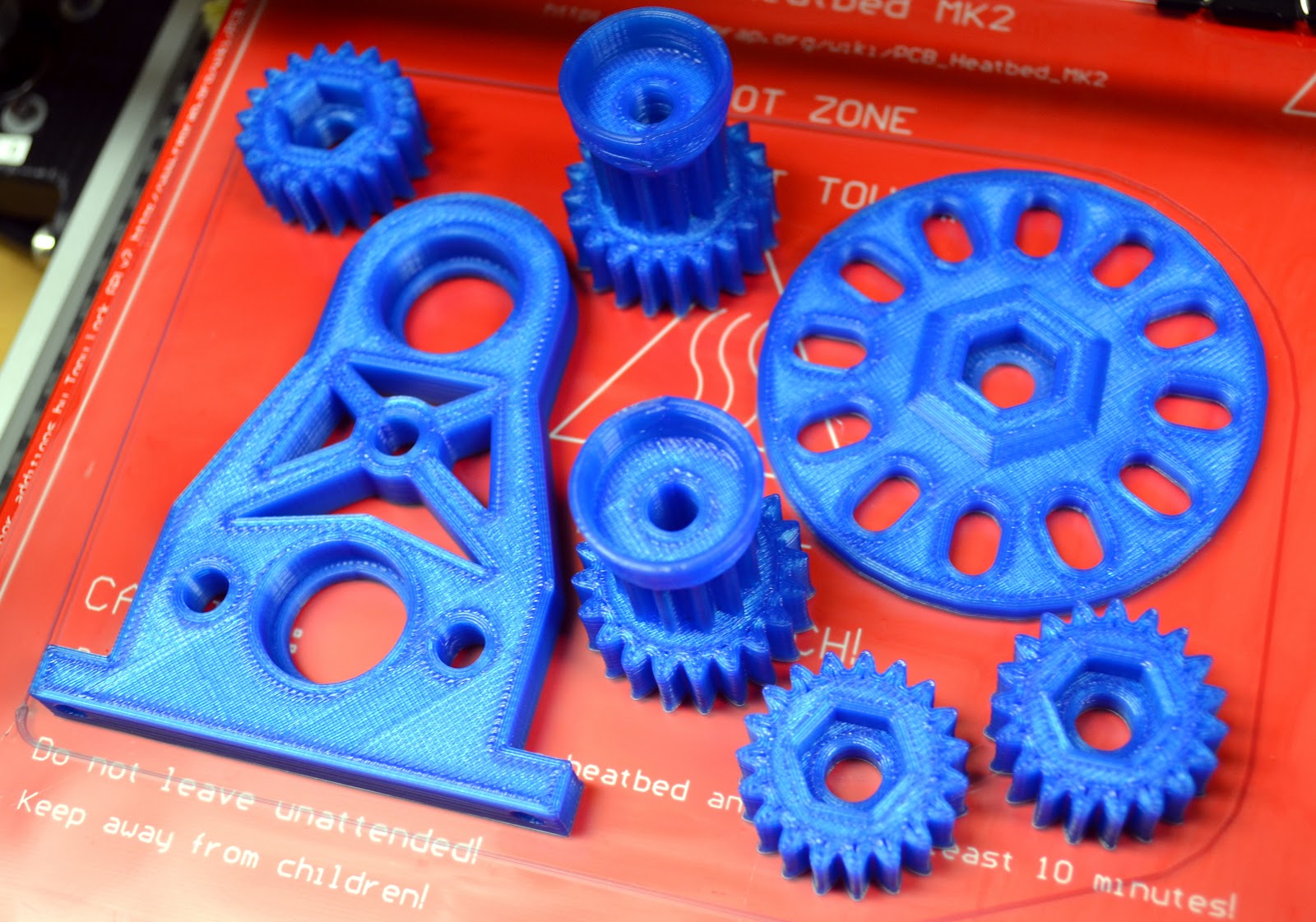
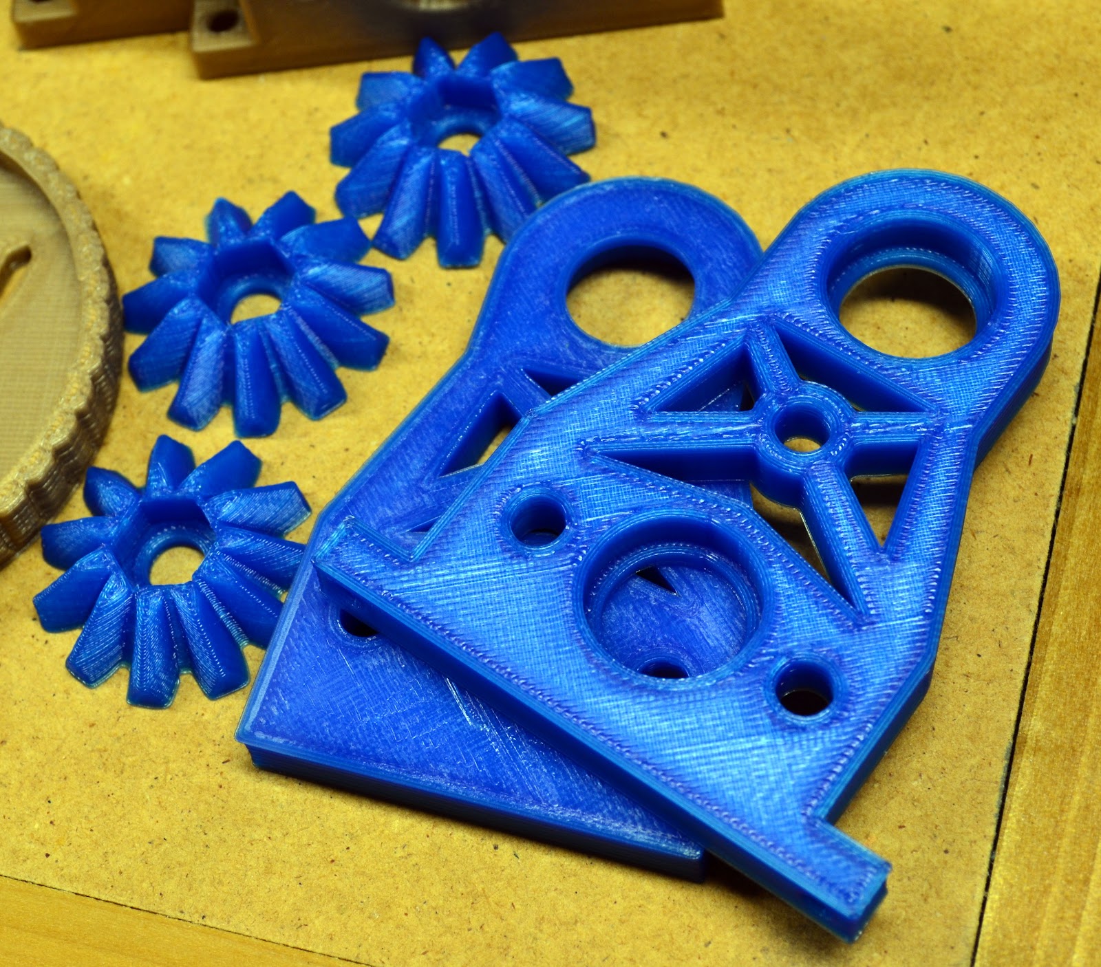
Here is a pic from a better camera (the image above was from my Galaxy Note) showing the blue parts from last night's print.  The blue PLA does look very cool (blue is my favorite color, so that helps).  The gold is also nice, but after a couple of months I was starting to get tired of it.  I have a spool of green still in the box that I haven't even opened yet.

Plate 2 of 5 of Mini Lathe Print in Blue PLA

Plate 4 of 5 is now printing (saving 3 of 5 for last I guess), and it also appears to be adhering well.  Here are a couple of shots of the first layer perimeters going down.

Plate 4 of 5 of Mini Lathe Print, Bottom Layer


Plate 4 of 5 of Mini Lathe Print, Bottom Layer Image 2

As you can see, I'm really squishing the first layer of plastic onto the glass plate.  The small flange that this forms around the bottom of the part does not seem like a big issue for these parts, so I'll take that small imperfection in order to be sure that nothing is going to come loose during the print.

I'm going to let the plate 4 print run overnight, and I have another piece of glass waiting to place on the printer tomorrow morning to start plate 3 of 5--the last plate to print--before I head to work.  It is so satisfying to be back where I can start a print and let it run without worrying about parts coming loose again. Really makes all the difference in the world in terms of output, since I can only spend a couple of hours at a time actually monitoring the printer.

One other note about using the PVA mixture--it did leave a milky white film and some white material on the bottom of the parts.  I first tried a little rubbing alcohol to see if I could wipe it off, then decided to try a small torch for some heat.  That worked like a charm, and I plan to record and post a video showing the torch making the white film disappear the next time I use this method.

Overall, the PVA seems to be an acceptable solution for getting the parts to stick well going forward.  Removal of the parts from the glass after printing is the only thing I'm not happy about for now, but I will try to re-warm the plate and see what happens.

As I type the current print has finished several layers and all seems well.  Time for some sleep while my MendelMax works on through the night . . .

D

Monday, October 8, 2012

I'm Back . . . I Think

Just a quick post to say that I'm seeing good results with a 1:8 PVA:Water mixture on top of heated glass with the infamous (if only in my own mind) blue PLA.  I'm confident enough in what I've seen on the first three layers to let the print go for the next four hours while I sleep, and hopefully I will wake up to the first complete parts I've seen come off the printer in somewhere around a month!

More tomorrow night . . .

D